What Influences Electrolytic Capacitor Lifespan?

If you speak with a bunch of design engineers, you might quickly believe that the electrolytic capacitor has a particularly dubious reputation. This view certainly hasn’t been helped by the so-called “capacitor plague” that occurred in the first few years of the new millennium. A faulty electrolyte mix used in these types of capacitors led to premature device failures, and quite often, a “bit of a mess” was made to the PCBs on which they were soldered. Because of the high-profile nature of the goods that used certain brands of “plagued” capacitors, this became big news. See this Wikipedia link if you’d like to see more details.
However, despite the problem of the capacitor plague (that Wikipedia reported as being down to a botched attempt at industrial espionage resulting in an incorrect electrolyte formula being used), this article focuses on helping the designer understand how to get many more years of useful life from an electrolytic capacitor. We won't get too deep into comparing electrolytic capacitor lifespan values for various components. The bottom line is that you get what you pay for, and like it or not, electrolytic capacitors are a necessity in many designs.
What Causes Electrolytic Capacitor Failure?
The primary mechanism that causes the degradation and failure of electrolytic capacitors is slow evaporation of the electrolyte over time, and of course, this is made worse at higher temperatures. This results in lower capacitance and higher effective series resistance (ESR). It’s a bit of a vicious circle because as ESR rises, so does any self-heating effect due to ripple currents. This can then lead to significant localized temperature rises that can accelerate the problem even further. In the past, this has influenced some companies to implement a rule of planned maintenance, where electrolytic capacitors are swapped out with suitable replacement components every few years, particularly when the system is used in critical applications.
Capacitor Specifications
You often see that an electrolytic capacitor will have a lifetime figure stated, such as 5000 hours. We’re going to use the TDK (previously EPCOS) datasheet as an example of how to interpret this information. This datasheet is for a B41888 capacitor, and it’s one that I’ve used in fairly critical products that had a long expected lifetime. The datasheet summary is as follows:
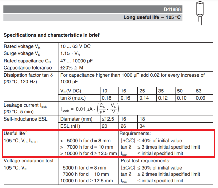
I’ve highlighted the relevant areas in red. It tells you that an 8 mm diameter capacitor will give 5000 hours of useful life. That’s a life of just 208 days, which on the face of it, is a very low value. However, that figure is for an operating temperature of 105 °C. If the operating temperature were 10 °C cooler, at 95 °C, then the lifespan would double. It will double for every 10 °C decreases below 105 °C. So, if the running ambient temperature of a capacitor in a particular circuit was maintained below 55 °C, you can use the following formula to calculate the actual lifespan:
Actual useful lifespan = [Lifespan at 105 °C] ∙2x
Where “x” is (105 °C - TACTUAL) divided by 10. At a temperature of 55 °C, “x” = 5, and therefore helpful lifespan stretches from 5,000 hours at 105 °C to 32 x 5000 hours at 55 °C. That’s now 18 years and so much more practical.
What Does a Capacitor's “Useful Lifespan” Mean?
Concerning the above datasheet, the right-hand highlighted column informs you that the capacitance may degrade from its original value down to a value that may be up to 40% lower over the component’s useful lifespan. So, if you select a 1000 μF capacitor for your design, you could expect its lowest initial value to be 800 μF based on the device’s 20% tolerance specified in the datasheet. Consequently, at the end of its “useful lifespan,” the worst-case scenario is that it might have dropped down to 60% of this 800 μF initial value, which is just 480 μF. As the designer, only you can say whether this will deliver adequate end-of-life performance for your product. It’s critically important that you, as a designer, take this degradation factor into account.
Dissipation Factor
For the B41888 device, the datasheet tells us that “tan” might increase by a factor of three times over the lifespan. Tan is the dissipation factor or the ratio of ESR to capacitive reactance, and it should not be confused with loss tangent. For reference, it is also the inverse of the Q-factor. With a 35-volt rated B41888 device, tan is listed as 0.12 at 120 Hz. A 1000 μFcapacitor has a reactance of 1.326 Ω at 120 Hz, which means that the ESR is 0.159 Ω.
That’s the figure for a capacitor of exactly 1000 μF, but we’ve seen it could be as high as 0.199 Ω for a capacitor sitting at the low end of the initial tolerance range (i.e., 800 μF). At its end-of-life, we’ve seen that the capacitance might only be 480 μF, and so it follows that the ESR could rise to 0.332 Ω. Finally, because tan can degrade by a factor of three over the lifespan, ESR might potentially increase up to 0.995 Ω.
You began your design with a capacitor that was nominally 1000 μF (with an ESR of 0.159 Ω), and now you could end up with a capacitor that is 480 μF with an ESR of about 1 Ω. Will your design be able to cope with this? How will it affect performance? Hint - simulation tools are your ally in this situation; use them to see the effects.
Other Factors That Affect Electrolytic Capacitor Lifetime
Ripple current
The B41888 lifespan figure assumes it’s operated at full ripple current. However, you will also find this useful graph in the datasheet that is applicable for a capacitor of 8 mm diameter:
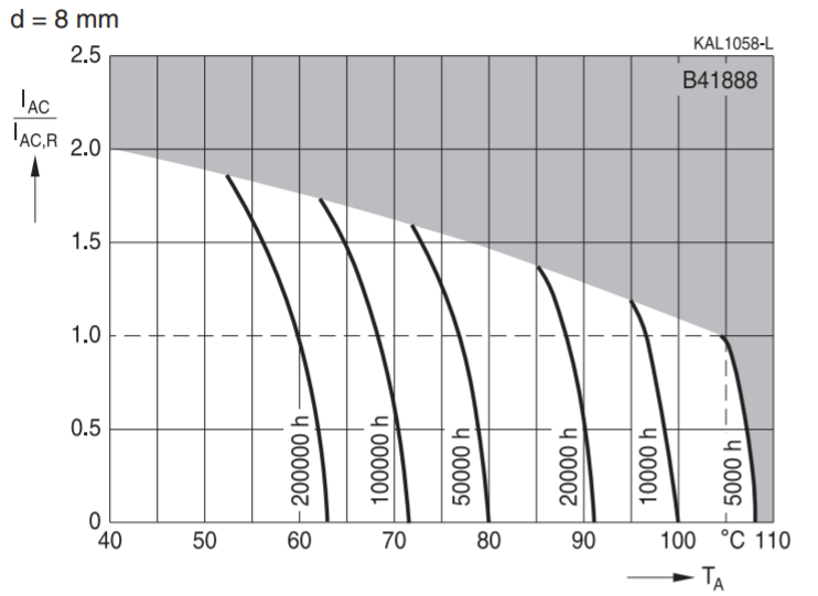
If you choose to operate at 50% of the rated ripple current (0.5 on the Y-axis), it’s equivalent to running at a local ambient temperature that is 3 °C cooler. That’s a 23% potential increase in lifespan, and sometimes, every little extra bit can count. If you needed to push the envelope on ripple current, you could also get the information you need from this graph. For example, if you run the component at 50% over the nominally rated ripple current at 65 °C, you would still achieve 100,000 hours of useful lifespan as you would get when operating at half the rated ripple current at 71 °C. It’s important to note that the graph’s darkened portion is a no-go area if you don’t want to damage the component.
Capacitor Operating Voltage
You can achieve a decent lifespan increase when the operating voltage is lower than the maximum rated voltage. The most conservative estimate is that lifespan doubles when the component is operated at 50% of the rated voltage. Of course, it becomes proportionately smaller as the operating voltage gets closer to the maximum rated voltage. I have seen less conservative estimates but, in the absence of any data in the manufacturer’s information to suggest otherwise, I would advise that you stick to this linear relationship and don’t expect any further improvement in lifespan beyond it doubling.
Read the Datasheet
There is lots of convenient information in the datasheet. For instance, for the B41888 capacitor that we have focused on here, the datasheet extract indicates that although the 8 mm diameter device has a lifetime of 5,000 hours, a 12.5 mm diameter (or greater) device has double this at 10,000 hours. If your target value of capacitance permits a choice in diameter and you have space on your board, it would be beneficial to choose a larger part to improve the lifespan. For instance, if you chose a 100 μF, a 35-volt component that you intended to run at 30 volts, you would get good lifespan benefits by selecting the 63 volts-rated part instead.
The 35-volt part has an 8 mm diameter, while the 63-volt part is 10 mm. However, the 10 mm part has a lifespan of 7,000 hours, and that could double to 14,000 hours just by running it at 48% of the rated voltage. The 8 mm part has a lifespan of 5,000 hours that would only increase to 5833 hours if operated at 30 volts. So, a relatively tiny 2 mm increase in diameter gets you a significant increase in lifespan.
Another consideration is the relationship between the ripple frequency and current rating. For instance, if your design requires a 1000 μF, 35-volt component, the datasheet will tell you that it has a rated ripple current at 105 °C of 2.459 amps, but this is at a specified 100 kHz. So, if the application runs at a lower frequency, you have to use the graph below to determine the effect:
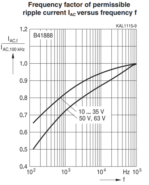
At low frequencies, such as 120 Hz, the rated ripple current is only 65% of the value at 100 kHz. This means that for the correct lifespan assessment in a 120 Hz application, you are restricted to a more limited-rated ripple current of just 1.598 amps.
Capacitor Failure Rates
Don’t mistake the gradual degradation in an electrolytic capacitor’s performance over its anticipated lifespan as anything to do with failure rates or MTBF. Any electronic component’s sudden and unexpected failure is different from how the component might “age.” Of course, if the circuit you designed stops working due to the aging of an electrolytic capacitor, that is a device failure from the user’s perspective. However, the designer’s failure is not to recognize how the component’s performance naturally degrades over time. In other words, it’s a design failure and not a component failure.
An electrolytic capacitor will have an MTBF measured in millions of hours. Although this can be degraded by both the amount of energy it stores and its ambient operating temperature, it’s still a ballpark away from being close to the much lower usable lifespan of the component.
Why Use Electrolytic Capacitors at All?
If electrolytics have such problems, why are they so widely used? There are several reasons, but chief among them is the ability to get high voltage ratings with high capacitances that are generally required on power supply designs. Due to the chemistry in electrolytes, there is no other component type that gives you the same combination of high capacitance and high voltage. With other components, the part either becomes physically huge, or a huge number of parts need to be placed in parallel.
In one past project, I needed to use 20 paralleled electrolytic capacitors (3,300 μF, 35 volts) to create a significant energy storage device in a recent design. I mention this because it will help you understand the difference between lifespan and MTBF. The circuit received a low mA charge current but was subject to sporadic load current pulses that were measured in amps.
Concerning the whole storage device’s lifespan, I fully expect the parallel components to degrade equally over time. In other words, the lifespan of all 20 components is expected to be the same as the lifespan of a single device. However, for MTBF, the single device’s value would need to be divided by 20 because the components are paralleled, and any one of the 20 could fail to short-circuit, which would cause the device’s failure.
Where to Find Reliable Capacitor Parts
The capacitor plague problem that we mentioned at the start of this article is regarded as a “proper failure” (i.e., related to failure rates) and is not the same as a component wearing out over its lifespan. Does a dripping faucet constitute a failure in your bathroom? The answer is obviously "no," it’s just usually down to normal wear and tear, which is to be expected.
When you need to find ultra-reliable parts with long electrolytic capacitor lifetime, use the Manufacturer Part Search Panel in Altium Designer®. You can also use the Altium 365™ platform to find in-production parts, manage your design data, and release files to your manufacturer. We have only scratched the surface of what is possible to do with Altium Designer on Altium 365. You can check the product page for a more in-depth feature description or one of the On-Demand Webinars.
About Author
Related Resources


Related Technical Documentation
Table of Contents
Take advantage of the world's
most trusted PCB design system.
One interface. One data
model. Endless possibilities.
Effortlessly collaborate with
mechanical designers.
The world's most trusted
PCB design platform
Best in class interactive
routing
View License Options
Thank you, you are now subscribed to updates.