PCB Heat Sinks: Thermal Pad vs. Paste in Your Circuit Board Design

Using thermal pads vs paste is an important decision when deciding how to best attach a heat sink to a power-hungry component like a CPU. Each of these materials gives the important benefit of heat transfer and reduced temperature, but there are other points to be considered when using a heat sink with a thermal pad or thermal paste. Assembly houses also need to know which option a design will use, requiring that clear documentation be provided from design data.
When you plan to include a heat sink in a new circuit board, you can keep your designs running cool with the complete set of circuit board layout features in Altium Designer. Hot components that need heat sinks or fans can be easily placed with a complete set of CAD tools, and complex mechanical components can be modeled in 3D with the integrated MCAD toolset. Download a free trial to see the difference Altium Designer can make in your new products.
ALTIUM DESIGNER
A unified PCB design application with a full suite of circuit board layout and manufacturing tools for professional designers.
Do you remember the first time you opened an old computer and saw a bulky metal heat sink on a CPU? Heat sinks and other cooling methods won’t go away anytime soon, and it’s often up to the board designer to determine whether a heat sink will be needed to remove heat from critical components. There are some simple strategies you can use to ensure your board will remain cool and that components will not get too hot during operation.
When working with heat sinks in a new design, engineers need to determine how they will attach a heat sink to the device. This often needs to happen in conjunction with an assembler, who will try to automate the process to ensure the heat sink is securely attached to its host component. Thermal pads and thermal paste are the two primary methods for attaching a heat sink to a hot component, giving a secure fixture with high thermal conductivity and heat transfer into the heat sink.
Choosing Between a Thermal Pad vs. Paste
Thermal pads and thermal paste are two methods for securely mounting heat sinks to integrated circuits, particularly to CPUs, GPUs, FPGAs, and other components with high power consumption. Some points to consider when selecting thermal pads vs. thermal paste include:
- Assembly: Which of these two materials can your assembler’s processes support?
- Replacement: Will the end user ever need to replace the heat sink?
- Durability: How long will the product be deployed in the field and under what conditions?
- Cost: How will each option affect per-board materials and assembly costs?
- Shape: Does the heat sink have an odd shape, and does the shape match that of a typical thermal pad?
Each type of material has its own advantages in different areas. Thermal paste can be messy and difficult to remove if the heat sink is ever replaced, making thermal pads a better option. However, thermal paste can be deposited in almost any shape, it costs less, and is much more durable. The table below shows a summary of the advantages of each type of material for mounting heat sinks.
Implement a Comprehensive Cooling Strategy
Thermal pads and thermal paste are important for mounting heat sinks and providing an interface with high thermal conductivity, but they are not the only option for cooling your circuit board. Cooling fans, additional copper, unique substrate materials, and metal cores are all viable options for removing additional heat from your PCB. Many boards with powerful processors will need to use a combination of strategies to keep temperatures within safe operating limits.
- Thermal pads and thermal paste are the two primary options for mounting heat sinks to hot components.
See a thorough comparison between thermal pads and thermal paste.
- Heat sinks can be combined with other cooling measures to keep your components and your board cool during operation.
Learn more about cooling strategy and heat sink design in your circuit board.
- Heat sinks can be a source of EMI if not used correctly in a printed circuit board layout.
Learn more about EMI from heat sinks and how to place heat sinks in your circuit board layout.

Additional copper in your circuit board layout can help remove heat from high-temperature components and can be used with heat sinks, thermal pads, and thermal paste.
Circuit Board Design Tools for Placing Heat Sinks
Heat sinks and the components to which they are mounted need to be placed just like any other component. They will have some mechanical outline that will determine spacing to other components, and they will need to have a PCB supply chain included as component data. Heat sinks can be placed as their own mechanical component, although it is often easier to include them in the processor’s PCB footprint and as a combined STEP model for 3D visualization.
When you need to place a heat sink in your circuit board, you’ll eventually need to place a 3D model in your PCB layout and check its placement against your enclosure. The heat sink position needs to be checked against your component locations to ensure accurate assembly and prevent interference. Once you’ve verified placement and heat sink size, you can think about how to mount the heat sink to the component to ensure high heat transfer using thermal pads or thermal paste.
Automatically Generate Your Assembly Documents in Altium Designer
Once you’re ready to plan for assembly, you can generate assembly documentation for your circuit board layout in Altium Designer. Thermal pads or thermal paste documentation can be included directly in assembly drawings using the integrated Draftsman utility, or it can be added to the bill of materials as a DNP component. Altium Designer streamlines these processes by taking data directly from your PCB layout and creating your PCB assembly documentation in a single application.
- Your PCB fabricator needs a complete set of documentation files and information to correctly assemble your board. Altium Designer includes the tools you need for accurate heat sink design and for specifying thermal pads vs. paste in your PCBA.
See how circuit board fabricators use your manufacturing documentation.
- Altium Designer helps streamline drawing creation with the Draftsman extension, making it easy to create accurate assembly and fabrication drawings for your circuit board.
Learn more about Draftsman and how to quickly generate assembly drawings.
- The world-class ECAD features in Altium Designer also integrate with native and external MCAD tools, giving you everything needed for heat sink placement.
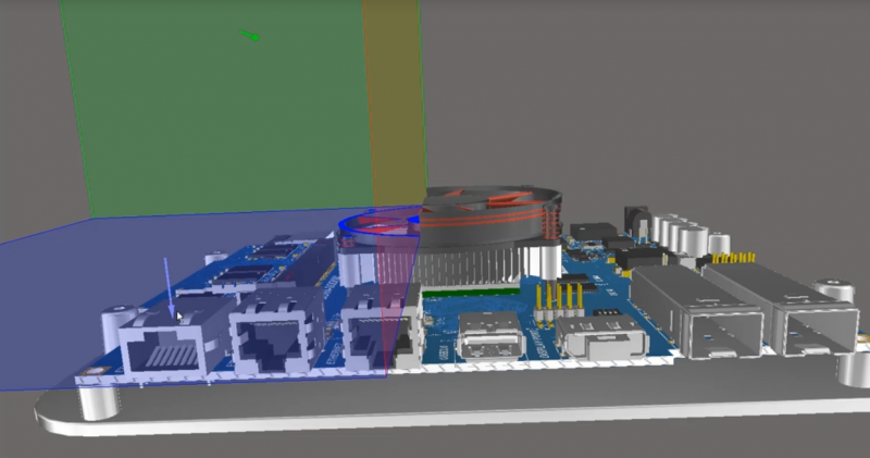
Altium Designer’s integrated ECAD and MCAD tools make it easy to select and place heat sinks and fans in your 3D PCB layout.
PCB Design Rules for Heat Sinks and Cooling Components
Design rules can apply to any portion of a PCB layout, including mechanical elements like heat sinks, fans, mounting holes, slots, and much more. Designs requiring a heat sink will need clearance rules to ensure component overlap and interference can be caught early in the design process. This is quite important for multiboard systems, which cannot function properly when there is overlap between a heat sink and other components or a collision with another board.
The same set of design rules that apply to heat sinks can also be applied to all other components in a circuit board layout when you use the right design tools. Altium Designer’s PCB design tools run on top of a rules-driven design engine, ensuring all your design tools are checking your board against design requirements as it’s created. Rules-driven design software does more than just check your board against design requirements, it helps you stay productive as you work to create advanced electronics.
Altium Designer Helps You Create Electronics With Maximum Productivity
The rules-driven design engine in Altium Designer unifies every design tool you need into a single application. Everything needed for design, layout, component sourcing, and manufacturing can be found in Altium Designer’s unified environment. You can stay productive and ensure ultra-accurate assembly with Altium Designer.
- Altium Designer includes everything needed to design simple circuit boards and advanced PCBAs in a single application.
Learn more about Altium Designer’s unified design environment.
- Altium Designer’s native 3D PCB design tools are ideal for placing heat sinks and ensuring your design will fit in its enclosure.
Learn more about the native 3D PCB design tools in Altium Designer.
- When you’re ready to share your circuit board with other PCB designers or your manufacturer, Altium 365 lets you instantly share your design and production data through Altium Designer or on the web.
Learn more about sharing your PCB project data with Altium 365.

Use the complete set of layout tools in Altium Designer to create high-quality PCB layouts with fans and heat sinks.
Whether you want to use thermal pads, thermal paste, or another unique thermal interface material, you can take full control over your design with Altium Designer. Quickly generate documentation for assembly and model your design in 3D with the complete set of circuit board design tools in Altium Designer.
Altium Designer on Altium 365 delivers unprecedented integration to the electronics industry until now relegated to the world of software development, allowing designers to work from home and reach unprecedented levels of efficiency.
We have only scratched the surface of what is possible to do with Altium Designer on Altium 365. You can check the product page for a more in-depth feature description or one of the On-Demand Webinars.
|
Thermal Pads |
Thermal Paste |
|
|
Ease of assembly |
X |
|
|
Ease of replacement |
X |
|
|
Durability |
X |
|
|
Cost |
X |
|
|
Shape |
X |

