


What is PCB Component Creation?

At a Glance
Learn more about PCB component creation and how you can easily create components with the best CAD features in Altium Designer.


Every electronic device needs components to operate properly, and models of components need to be created for use in CAD programs. All PCB components contain specific sets of information, all of which is stored in schematic symbols, the PCB footprint, and 3D models of a component. All components need to include this information so that they can be displayed, placed, and routed in a PCB design. One question that always comes up is: what exactly are each of these features in a PCB component, and how are they created?
PCB component creation is easy and only requires some standard CAD tools. Component data is created by drawing specific information into a CAD application, and the component data is packaged in a library for reuse in new projects. In this article, we’ll look more at PCB component creation and some of the CAD tools you can use in your design software to create your components.
Select the Components You Need
Component selection is all part of the front-end engineering process, and it relies on having access to the right set of supply chain data and electrical specifications for your components. Any components you select for your board should be sourceable, meaning they are in-stock and can be procured from authorized sources. You’ll also need technical data for your components so you can create CAD models, simulations, and enclosure designs as needed.
Unfortunately, even if you find the perfect part for your board, it might not come with an attached symbol or footprint. In this case, you’ll need to create these CAD data by hand. PCB design software comes with utilities to create the basic pieces of any electronic component so that it can be included in your PCB layout.
Important Information in PCB Components
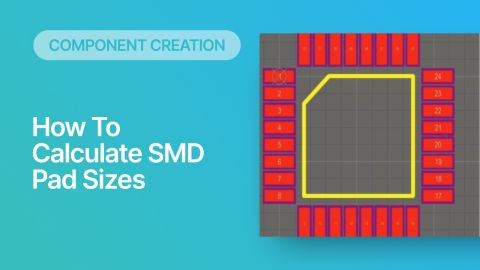
The two basic pieces of any component are a schematic symbol and a PCB footprint. Schematic symbols are used in front-end engineering to define connectivity in your schematics, and this will define the corresponding nets in your PCB layout. Schematic symbols do not contain any of the physical information in a design, only the electrical connections that need to be reflected in a PCB.

The PCB footprint, on the other hand, includes the physical data needed to show the component in a 2D drawing. The information in a PCB footprint will later be used to create Gerbers and assembly data for your PCB layout. The data you include in your PCB footprint needs to accurately reflect the pad and package information in your component datasheets.

The table below summarizes the data that needs to be placed in schematic symbols and PCB footprints so that a component can be accurately reflected in your schematics and PCB layout.
|
|
|
|
|
|
|
|
|
|
|
|
|
|
|
|
|
|
|
|
|
|
|
|
|
|
|
|
|
|
|
|
|
|
|
|
|
|
|
Much of the information in the schematic symbol will be automatically mirrored over to the PCB footprint when you assign the footprint to a component. You won't have to copy this information over to the footprint. Additionally, when you sync the schematic and PCB layout during a design update, the information in the symbol will be provided over to the footprint so that the component data always matches across both documents.
The last important piece of information needed for a PCB component is a 3D model. While this is not required to have a PCB manufactured, modern designs often require some level of mechanical checking and visualization in 3D. MCAD tools can be used for enclosure design, checking mechanical interferences, and creating a board shape for the PCB layout.

Creating Component Libraries
Once components are created for a PCB, they are typically compiled into a library. With libraries, a designer can include all the component data needed for a PCB layout and set of schematic sheets in a single file. The component data can then be shared with a collaborator, manufacturer, or customer as needed.
Libraries can contain schematic symbols, footprints, or complete components (both symbols and PCB footprints). Many companies that need to track thousands of components across multiple projects will hire a full-time PCB librarian. This person’s job is to ensure all component data is accurate and up-to-date before it is included in a new project for a customer. Component data needs to be checked for accuracy and obsolescence so that new designs can be sourced at scale when needed.
After components have been created and design data has been verified, it’s time to add components into your schematics and PCB layout. Libraries are instrumental for ensuring each design you need to create has accurate, up-to-date component data.
- Learn more about your component libraries
- Learn more about leveraging the cloud to manage component libraries
Component Data in Schematics and a PCB Layout
Once your components and libraries are created, a new project can be started with these components. Starting a new project with an existing validated set of components is a great way to cut down design time. Each time you need to reuse a component, simply pull it from the existing libraries and place it in the schematics where it’s needed.
When components in the design have attached 3D models (normally with STEP files), the design can be checked in 3D, often directly in your PCB design software. Once the PCB layout is complete, components in the design should be checked against mechanical constraints to ensure there is no undesired interference or collisions between components, the board, and the enclosure. Clearances and interferences can automatically be checked in 3D using the best PCB design tools by pulling 2D and 3D design data directly from your PCB libraries.
- Learn more about the creating schematics for your PCB
- Learn more about creating a PCB layout from a schematic

PCB component creation, sourcing, management, and much more is easy with the complete set of design features in Altium Designer®. Every Altium Designer user has access to a dedicated workspace in the Altium 365™ where projects, component data, manufacturing data, and any other project documentation can be stored and shared with collaborators. Altium Designer also integrates with popular MCAD and simulation applications, giving you the ability to approach systems design while considering the mechanical constraints of your enclosure and components.
We have only scratched the surface of what’s possible with Altium Designer on Altium 365. Start your free trial of Altium Designer + Altium 365 today.

About Author
Related Resources
Related Technical Documentation
Table of Contents
Design to Release, Without the Friction
- Keep reviews tied to the right version
- Reduce handoff confusion and rework
- Spot sourcing and release risk earlier
- Work solo, share when needed
Get Started
Thank you, you are now subscribed to updates.


