Designing with Shock Management for Avionics PCBs

Of all the electronics application areas, there is one that needs to consider mechanical and thermal shocks during design: avionics. An avionics designed system that is put into production within a satellite, aircraft, or spacecraft can experience strong vibration and mechanical shock during flight, and these systems need to be designed with high reliability in mind.
IPC standards, MIL-PRF standards, and other standards specify some design aspects that should be implemented in your circuit board layout, and you’ll need the best PCB design software to implement these in your physical design. Whether you’re designing rigid boards, flex circuits, or complex systems like backplanes and daughtercards, the best PCB CAD software will help you implement the components and layout choices to ensure reliability. In this tutorial, we’ll show how your PCB layout tools can help you design shock management for avionics systems, and which layout and design features you need to ensure reliability.
ALTIUM DESIGNER
A unified PCB design application with circuit design features, a powerful PCB editor, and manufacturing reliability features for professional avionics PCB designers.
Whether an electronic system is installed in an aircraft or a vehicle, it will most likely experience mechanical class 3 shock at some point in its lifetime. Ensuring reliability in shock management for avionics circuit boards happens at the board level, and the importance of shock management for avionics can’t be ignored. Rigid and flexible circuits in avionics systems need to be designed to the highest industry reliability standards and manufactured with strict quality control systems in place. Mechanical reliability needs to focus on damping mechanical shocks to prevent the fracture of critical components. However, these same concerns also apply to printed circuit design for avionic systems.
With the best design tools, you can encode your important design reliability standards as design rules in your aerospace high-speed PCB design software. The best circuit board layout and routing tools can automatically apply design features to your interconnect to ensure high reliability and manufacturability. The best layout tools will also check your board against important aerospace high-speed PCB design standards as your board is created.
Keep reading to learn more about the important shock management for avionics and electronics components standards your board must follow to ensure reliability.
Techniques and Standards for Mechanical Shocks Design for Avionics Design
Electronics in avionics systems must be designed to withstand strong mechanical class 3 shocks to ensure reliability. Some important standards set design requirements for avionics systems, including reliability standards and testing standards. Three of the most important MIL standards include:
- MIL-PRF-38534 Screening and Quality Conformance Inspection Requirements
- MIL-STD-883 Microcircuits Test Standards
- MIL-STD-810 Shock Testing Overview
A deeper outline of the best mechanical shock design, vibration design, and testing standards for rugged electronics can be found in MIL-PRF and MIL-STD standards.
Other standards that are highly specific to PCB design and fabrication are the IPC-6012 standards, which define three classes of electronic products. Aerospace high-speed PCB design and electronics fall within Class III, which includes any product where human lives depend on its reliability and uptime. These standards define some basic features that should be placed on a bare circuit board to ensure high reliability and uptime during design.
Design to Quality and Reliability Standards With the Best PCB CAD Software
Altium Designer’s PCB layout tools allow you to automatically apply important avionics reliability standards to your design by instantly applying copper features to a bare board to ensure product reliability. Once a design has been created and fabricated, design data can be easily exported for use in reliability testing through a set of integrated board report generation tools.
- Your PCB layer stack-up design is one determinant of reliability. Be sure to pick the correct copper weight to prevent overheating and ensure mechanical strength in the PCB stack-up.
- For HDI designs, there is some debate as to the reliability of microvias, particularly to thermal and mechanical shocks. Avionics designers should be aware of the limitations or microvias in their designs.
Learn more about microvia reliability and testing to IPC standards.
- When you need to assess aspects like mechanical and thermal reliability, as well as EMI performance, Altium Designer users can import their PCBs into Ansys field solvers for powerful numerical simulations.
Learn more about interfacing your design with Ansys field solvers.

Teardrops are one feature implemented in Class 3 designs to help prevent breakouts due to thermal or mechanical Class 3 shock.
Components That Determine Design Reliability
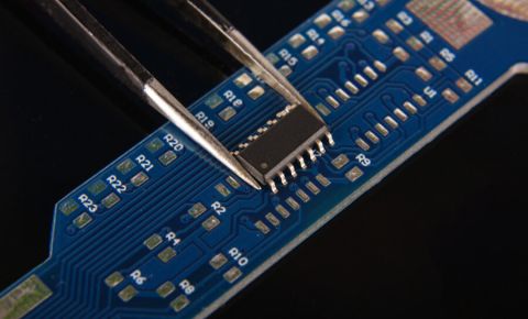
Your components can be a major determinant of product reliability. Through-hole components are preferred in mission-critical systems as they are more able to withstand mechanical shocks. For systems that may experience repeated shocks or strong vibrations, solder balls on SMD components should be tested to ensure strength and reliability. Once you decide on the components you need, they will need to be procured at the required scale. The best aerospace high-speed PCB design software will include supply chain tools to help you import component data and CAD models into a PCB project and instantly generate the required documentation for a manufacturer.
Find the Most Reliable Components for Your Avionics Systems
The features in a PCB layout are one part of ensuring reliability, but the components used in a printed circuit board will also play a role in ensuring reliability. It’s also important to select component vendors that comply with ITAR/EAR requirements on procurement and import/export, and design teams need tools to help manage their supply chain.
Altium Designer not only helps you find components from compliant manufacturers, but it also gives you visibility into component stocks from compliant and vetted distributors. Supply chain visibility is critical for designing to cost, ensuring import/export compliance, and obtaining reliable components within acceptable time frames. Only Altium Designer gives you real-time supply chain visibility from worldwide component distributors alongside the rest of your design tools, which helps you stay productive and compliant.
- Navigating supply chain disruptions in avionics design is easy when your design software helps you find in-stock, in-production components for your PCB.
Learn more about supply chain visibility in Altium Designer’s sourcing features.
- Once you’ve narrowed it down to the best components for your avionics design systems, Altium Designer gives you supply chain tools to import CAD models and source data for your PCB.
Learn more about the Manufacturer Part Search Panel in Altium Designer.
- Once you’ve found the best components for your avionics design, use the ActiveBOM feature to instantly generate a complete and accurate bill of materials for your project.

Once you’ve identified reliable components for your circuit board layout, you can grab CAD data and import sourcing information into your BOM with the supply chain visibility tools in Altium Designer.
Experience Rules-Driven Design in Altium Designer
With the rules-driven printed circuit design features in Altium Designer, your important reliability and shock management for avionics design and electronics components requirements can be encoded as design rules. As you create your PCB, your layout will be automatically checked against these standards and flagged for any required changes. The rules-driven design engine in Altium Designer gives you everything needed to design complete avionics design systems from concept to finished product.
Once you’ve finished your circuit board layout and verified it against avionics reliability standards, deliverable generation is quick and easy. To help you make the transition to production, Altium Designer includes a complete set of manufacturing preparation tools that automate PCB fabrication and assembly file generation in standard formats. You can take advantage of the following high-volume manufacturing features in Altium Designer:
- Create fabrication and assembly drawings with the Draftsman utility
- Generate Gerber files in the latest file formats (RS-274-X and X2)
- Prepare a bill of materials and automatically import sourcing and supply chain data
- Generate NC drill files, pick-and-place files, netlists, and board reports
Unlike other design programs, Altium Designer allows avionics designers to customize their design and fabrication documentation to meet internal requirements and industry standards. The manufacturing file generator features in Altium Designer give you complete control over your drawings without creating a complex workflow for fabrication and assembly. Best of all, you don’t need an external CAD application to create these files for your manufacturer.
Altium Designer Keeps You Productive
Instead of separating your important design tools into separate programs, Altium Designer places everything you need for design, layout, and manufacturing into a single program. Everything needed to design ultra-reliable high-quality avionics systems is included in Altium Designer. With the managed cloud collaboration features in Altium 365, avionics designers have additional tools to help them design complex systems, see the electronics supply chain, and manage their design data in one location.
- Altium Designer is a complete PCB design application for any application area, including avionics. Access everything you need for high-quality PCB designs in Altium Designer.
Learn more about the integrated design environment in Altium Designer.
- Avionics systems carry strict mechanical constraints that are best satisfied with a unified ECAD-MCAD collaboration approach to PCB design. Altium Designer includes a complete set of native 3D PCB design tools for any application.
Learn more about the native 3D design tools in Altium Designer.
- Avionics systems can be complex to design and manufacture, but Altium 365 gives design teams a way to collaborate in a securely managed cloud environment. You can instantly share your design and production data through Altium Designer or on the web.
Learn more about sharing your avionics projects with Altium 365.

Altium Designer takes you from concept to finished product in a single program.
Everything needed for circuit design, PCB layout, and manufacturing for avionics systems can be found in Altium Designer. You can take control over all aspects of your design and manufacturing process with the complete set of PCB design tools in Altium Designer.
Altium Designer on Altium 365 delivers an unprecedented amount of integration to the electronics industry until now relegated to the world of software development, allowing designers to work from home and reach unprecedented levels of efficiency.
We have only scratched the surface of what is possible to do with Altium Designer on Altium 365. You can check the product page for a more in-depth feature description or one of the On-Demand Webinars.


