How to Design a Custom Arduino Shield Board

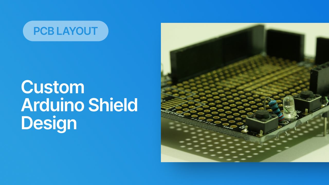
Are you ready to connect custom circuits to your Arduino, but you’re tired of using a breadboard to build up your circuits? It sounds like it’s time for you to design a custom Arduino shield. These boards have the same form factor and board-to-board connection that matches your favorite Arduino base board, but you have freedom to control many of the basic aspects of the layout in your shield board. You can even design these boards to be reconfigurable if you like, similar to the shield board shown above.
If you’ve never designed your own Arduino shield board, follow along with the instructions shown below. Throughout this article and in some upcoming articles/videos, we’ll show several tutorials on how to use Arduino and shield boards, including some tutorials on application development.
Starting Your Arduino Shield Design
The first step might be the most obvious, but it’s tempting to overlook the first step in starting an Arduino shield board design: find the mechanical dimensions of your Arduino shield and the connector pinouts. It’s tempting to jump into the design and start making schematics, but you’ll need the connector pinouts early in the design process so that you can place nets on the right pins in your design. Once you’ve finished schematic capture and you’re ready to import the design into a blank PCB layout, you’ll need to set the board dimensions to sit at the width of the Arduino base board.

It’s common for an Arduino shield to have dimensions that differ from the dimensions of the base board, but the main requirement is to set the width so that you hit the pins you need to use on the main Arduino board. You would want to span across the entire board so that the shield board is stable when mounted to the base board.
Once you’re ready to start designing the circuits and schematics for your board, hop into a schematic editor and start adding your components. Probably the most important components you’ll need are the pin headers to make the connection between your Arduino base board and your custom Arduino shield.
Pin Headers
Arduino base boards use pin headers with 0.1 inch (2.54 mm) pitch, with recommended hole sizes in the female header of 1.02 mm diameter. The pins are square with a 2.5 mm frame, as shown in the mechanical drawing below.

This component will provide the interface between your custom Arduino shield board and the base board. When you’re selecting the pin header for your shield board, you can use a male-male header with pins on both sides; this allows you to connect pins together easily with jumpers. You could also just use the pin header shown above, where the pins face down and plug into the base board, while the holes face up to accept wires or axial component leads. If you use the version above, you could conceivably plug another shield board into a stack, if you like.
Once you’ve selected the pin header, you’ll need to create or locate schematic symbols to use for the header in your schematic editor. The symbol you use should match the pinout on the Arduino base board; make sure you keep track of which side of the board each pin header will be located. If you’re unsure of which pin header you should use in your design, take a look at this option from TE Connectivity. Shrouded and keyed versions of these pin headers are also available if needed.
What Can You Put on Your Shield Board?
Once you’ve determined which base board you’re using and you have a basic plan for the layout, you can decide which circuits and components to include in the shield board. Technically, you can put anything you want on a shield board as long as it will fit in the allotted area. My company has done industrial shield boards for Arduino using relays and 120-240 AC power, and we’ve done simpler digital boards with multiple sensor interfaces. The options are limitless. Some of the typical components and circuits you’ll find on a shield board include:
- Power: Will the board need to have an external power supply (AC, 24 V DC, 12 V DC, etc.), or can components be powered by the 5 V pin on the base board? You might need to include a regulator (either an LDO or a switching converter).
- Connectors: Screw terminal blocks are useful for making mechanically tight connections to external wired devices. You could also place pin headers on the shield board to make connections.
- LEDs, buttons, and switches: LEDs are useful as indicator lights, either for power or logical states, or they can be used as an indicator for toggle switches. Switch circuits can also trigger logic states, either on GPIOs or on your shield board circuits.
- Specialized ASICs: There are plenty of ASICs on the market that perform a range of different electrical functions. These are easy to include in a custom Arduino shield as they generally connect over SPI or I2C, and they can be easily configured in your application.
If you want to have a reconfigurable board, you can design a perf board section into your Arduino with a hole array. This mimics breadboard functionality and gives you some flexibility in your design.
Perf Board Shields
A perf board section on your shield board gives you an area where you can solder custom circuits with through-hole components, and these circuits can interface with other fixed circuits on the shield board. You could also connect these circuits back to the pin header so that they connect directly to the MCU on the Arduino base board. If you look at the board below, you’ll see an example of what I mean. This shield board includes a perf board section where some custom circuits can be built, and small-gauge wire or jumpers can be used to make connections between components.

These boards are interesting in that they can be reconfigured simply by removing components, and they still allow you to make a connection back to the pin headers with wires. Make sure to use holes with appropriately sized pads so that through-hole components can be soldered easily. You’ll note that, in the above image, the hole spacing is far enough apart that it would be difficult to solder two pads together directly. Make sure the holes are large enough or there is a rail to place wires between a component pin and a nearby hole.
Some prepackaged perf boards come with a ground plane on the back side, and you can certainly take the same approach in your custom Arduino shield. This gives you an opportunity to implement some functionality that might normally require an external module, such as wireless or Ethernet.
Other Types of Custom Arduino Shields
It’s also common to see shield boards used in some of the following applications:
- Ethernet: This might be a bit ambitious for a newer designer, but you can actually build a shield with Ethernet using a standard controller IC with integrated PHY and a magjack RJ-45 connector. The magjack is important here as it will integrate the magnetics and termination circuits into the connector body.
- Sensor interface: These boards include amplifier circuits or ASICs that allow an Arduino to interface with specialty sensors. Aside from an op-amp in a DIP package, ASICs and other interfaces will be SMD components. These interfaces normally use SPI, I2C, GPIOs, or an ADC interface.
- Wireless shield: These boards will include a transceiver for wireless communication over a sub-1 GHz protocol (Zigbee, LoRa, etc.), or a WiFi/BLE transceiver. Signals are normally routed into the transceiver interface over a bus interface. Follow best practices with ground plane placement or antenna connections to ensure signal integrity.
- Displays: There are small OLED displays that can be used on a shield board. These will connect over SPI with a shrouded connector. If you want to make a compact device with a display, it’s best to mount the display on your shield board so that it will remain secure, then route connections over to the pin header.

Obviously, the list doesn’t end here, there are many other types of custom Arduino shields you can build. Make sure you take time to find the libraries you need to support any of these peripherals. Fortunately, the open source community has spent plenty of time developing Arduino libraries for different components, you can usually find these on GitHub. If you’re using a peripheral that was specifically designed for use with an Arduino, you can probably get libraries from the manufacturer.
Next Steps
In an upcoming article and some new videos, we’ll look more at getting started with Arduino application development. For now, take a look at this video from Ari Mahpour, he nicely shows how you can quickly boot up your Arduino with a simple Hello World application so that you can start programming your board with your shield.
Now that we’ve looked at some of the basic design points that go into a custom Arduino shield, your first step is to start creating circuits for your custom shield board. You can easily find the components you need to start building schematics and circuits using the PCB design features in Altium. You’ll have everything you need to find components, create schematic symbols and footprints, and transfer your design into a PCB layout.


 Back
Back