


What is a Multi-CAD Environment? Advantages and Best Practices

At a Glance
Learn how a multi-CAD environment streamlines design collaboration. See how teams reduce rework, improve visibility, and follow best practices for faster delivery.


Traditionally, mechanical engineers (MEs), electrical engineers (EEs), and PCB designers have operated in silos using separate CAD languages. This fragmentation leads to costly reworks and handover friction. Multi-CAD solves this by providing a bridging tool that allows designs to converge seamlessly, ensuring all stakeholders have the visibility needed to move projects forward without manual translation.
Key Takeaways
Multi-CAD eliminates silos and rework. It bridges different CAD tools (e.g., KiCAD, EAGLE, OrCAD) in a single environment, reducing manual translation, handover friction, and costly redesigns.
Browser-based visibility accelerates collaboration. Teams can instantly open and review third-party design data via Altium (no native tools required), enabling faster validation, vendor checks, and cross-team feedback.
- MCAD CoDesigner enables true concurrent engineering. Real-time, bidirectional ECAD–MCAD sync allows mechanical and electrical teams to work in parallel, share constraints early, and ensure first-time fit without back-and-forth.
- Value extends beyond design to sourcing and decision-making. Early visibility into BOM, alternates, and mechanical constraints helps PCB designers, EEs, and sourcing teams make better decisions, reduce risk, and avoid late-stage changes.
What Is a Multi-CAD Environment?
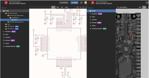
In the Altium ecosystem, “Multi-CAD” refers specifically to the ability to open and review design data created in other ECAD software, such as KiCAD, EAGLE, and OrCAD, directly within a web browser via Altium. This allows for rapid ‘sanity checks’ of schematics and layouts sent by vendors or customers without needing native software installations.
By leveraging a multi-CAD environment, teams can alleviate some of the long-standing pain points that come with working in separate CAD platforms. As mechanical engineers (MEs), electrical engineers (EEs), PCB designers, and even supply chain experts integrate their data into the design workflow, there is a better way to manage it without having to learn all kinds of new software.
Beyond Multi-CAD: MCAD Collaboration
Beyond Multi-CAD viewing capabilities, the MCAD CoDesigner serves as a dedicated bridge. Unlike the static viewing of third-party files, this separate feature focuses on real-time, bidirectional synchronization between the ECAD and MCAD domains.
Advantages for Mechanical Engineers
The MCAD CoDesigner serves as a sophisticated bridge between departments, allowing MEs to treat PCB layouts as dynamic, native assemblies within their preferred mechanical environment. This replaces the tedious process of manual cross-referencing between separate files with a unified, synchronized view.
Through this integration, MEs can leverage:
- Bidirectional Constraint Definition: MEs can proactively define board shapes, mounting holes, and critical keepout zones directly in MCAD. These constraints are “pushed” to the EE, ensuring the electrical layout respects the mechanical envelope from day one.
- Concurrent Workflows: Instead of waiting for a completed PCB design to check for fit, MEs can work in parallel, adjusting enclosures and refining thermal paths as the electrical design evolves.
- High-Fidelity Data Exchange: Beyond simple STEP files, this workflow synchronizes complex data, including elements specific to the bare PCB, into a single, high-fidelity model.
Integrating Multi-CAD ensures that PCB designers can clearly visualize mechanical limitations in real time. By defining static elements (such as connectors, heat sinks, and shielding) within the MCAD environment, MEs provide a “living” blueprint for the component layout, ensuring a perfect first-time fit.

Advantages for Electrical Engineers
EEs can benefit from faster design reviews and vendor validation. A Multi-CAD environment helps them overcome the “conversion hurdle” associated with importing, fixing problems, and exporting up-to-date designs. Moreover, the use of a web-based viewer simplifies the connection of data to various other sources, including mechanical design platforms external to Altium.
In short, EEs experience:
- Instant Verification: Verify designs against MCAD files in real-time.
- Design Integrity: Perform quick schematic/layout checks via Altium before desktop transfer.
- Reduced Overhead: EEs can perform instant schematic and layout verification on third-party files before committing to a full desktop import.
Advantages for PCB Designers
The Multi-CAD workflow allows PCB designers a better baseline of data for making decisions. By importing STEP files to create three-dimensional clarity, components are fit into true enclosure specifications and real-world placement. This avoids the need to design in 2D and confirm in 3D, and instead PCB designers are built to the real-world mechanical constraints.
PCB designers can:
- Eliminate guesswork with the use of STEP models for components. Designers can make accurate placement decisions and ensure correct clearance with the right data.
- Automate interference checks and flag collisions between components.
- Import a 3D enclosure directly into the PCB environment, allowing the designer to choose and place connectors and high-profile components as per the enclosure restraints.
Advantages for Sourcing and Supply Chain
Multi-CAD environments extend value beyond design by improving visibility into component and BOM data as designs evolve. For example, an approved alternate component may be electrically equivalent to the original part but require a different footprint or pinout. In a multi-CAD environment, these differences are identified earlier, allowing PCB designers to accommodate alternates proactively and enabling sourcing teams to mitigate supply risk without triggering late-stage redesigns or delays.
- Proactive Sourcing: Identify footprint or pinout changes in alternate components earlier to mitigate supply risk.
- BOM Alignment: Ensure design and procurement are synced on MOQ and obsolescence constraints.
Best Practices for Multi-CAD Adoption
1. Choose a Platform with Diverse CAD Integrations
A Multi-CAD workflow must preserve design intent without requiring engineers to master multiple tools. Whether moving data between SOLIDWORKS and Altium Designer, or bridging to KiCAD and OrCAD, the platform should facilitate a “frictionless” exchange that maintains data integrity across all environments.
2. Leverage Browser-Based Visibility
Maximize stakeholder collaboration by using a browser-friendly platform for real-time design and supply chain reviews. While desktop applications remain necessary for complex ECAD conversions, a web-based “overlay” allows non-CAD users to provide manufacturing and product feedback without heavy software overhead.
3. Define Parametric “Ownership”
Transitioning to a parallel workflow requires clear rules to prevent “intent collisions”. Establish a protocol for who owns specific parameters: typically, the ME owns the board shape and mounting holes, while the EE owns the component placement. This ensures that simultaneous updates don’t overwrite critical work.
4. Centralize Data Through Standardized Libraries
Eliminate “data drift” by moving away from fragmented file sharing and static exports. A unified library ensures that every 2D electrical footprint is mapped to a high-fidelity 3D mechanical model.
Multi‑CAD workflows are most effective when design context stays clear, connected, and easy to access throughout development. Altium Develop helps engineers keep mechanical, electrical, and sourcing inputs visible as designs evolve, reducing rework caused by misalignment or missing information. By supporting quick validation and smoother handoffs, without adding workflow overhead, teams can move from concept to review with greater confidence. Get started with Altium Develop →
Frequently Asked Questions about Multi-CAD Environment
What is a Multi-CAD environment?
Multi-CAD gives the ability to integrate insights from one CAD software into another. While users may not make changes to all design elements, they can visualize all relevant changes in their desired CAD tool. For instance, MCAD users can set ‘keepouts’ that appear in the component layout.
What is a CAD environment?
CAD is a digital software solution used to create 2D drawings and 3D models of products at all levels. Electrical and mechanical engineers, and PCB designers use different solutions to carry out their work.
What is CAD in PCB?
CAD is used by PCB designers to create schematics and layouts for electronics. Altium Designer, included in Altium Develop, is a popular tool that integrates other solutions used by engineers, procurement, and manufacturing.

About Author
Related Resources
Related Technical Documentation
Table of Contents
- Key Takeaways
- What Is a Multi-CAD Environment?
- Beyond Multi-CAD: MCAD Collaboration
- Advantages for Mechanical Engineers
- Advantages for Electrical Engineers
- Advantages for PCB Designers
- Advantages for Sourcing and Supply Chain
- Best Practices for Multi-CAD Adoption
- 1. Choose a Platform with Diverse CAD Integrations
- 2. Leverage Browser-Based Visibility
- 3. Define Parametric “Ownership”
- 4. Centralize Data Through Standardized Libraries
- Frequently Asked Questions about Multi-CAD Environment
- What is a Multi-CAD environment?
- What is a CAD environment?
- What is CAD in PCB?
Design to Release, Without the Friction
- Keep reviews tied to the right version
- Reduce handoff confusion and rework
- Spot sourcing and release risk earlier
- Work solo, share when needed
Get Started
Thank you, you are now subscribed to updates.