Current Limiting Resistor LED Systems with Matching Voltage Power Supply
Most of my friends in engineering live a balanced lifestyle. However, there are some engineers that are workaholics. These engineers do not limit their working hours and are constantly dealing with stress. Their lifestyle is not so different from an LED’s that is directly connected to a power supply without a current limiting resistor or with the wrong resistor value. They start out strong, but eventually flicker and burn out.
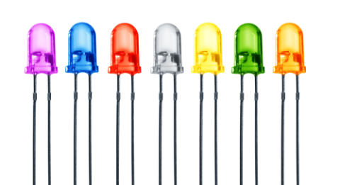
In the architecture industry, it is common for Light Emitting Diodes (LED) to be used in architecture models. However, I have noticed that more and more people are connecting their LEDs directly to the power supply without a current-limiting resistor. While they are initially functional since the voltage of the power supply is set to match the LED, this is not a good practice to follow if you want your LEDs to live up to their printed board specified life cycles.
How an LED works
An LED is a semiconductor device built using a junction of P-Type silicon and N-Type silicon, similar to a diode. P-Type semiconductors have a higher concentration of positive “holes” than electrons and N-Type semiconductors have a higher concentration of electrons.
A typical diode only allows current to flow in a single direction. A forward bias is applied to the LED by connecting the P-Type silicon to the positive terminal of a power supply, and the N-Type silicon to the ground. When the forward voltage exceeds the threshold voltage of the P-N junction, the current starts to flow. The voltage drop across an LED is always equivalent to the forward voltage of the LED. They may vary from 1.8V to 3.3V depending on the color and type of the LED.
When LED is connected to a power supply with a voltage higher than its forward voltage, a current limiting resistor is connected in series with the LED. The current limiting resistor limits the current for the LED and regulates the difference in voltage drops between the LED and the power supply. Of course, you’ll need to calculate which current limiting resistor you’ll need for your printed board.
Choosing The Right Power Supply for LEDs
While regular switching power supply could easily light up a current limiting resistor LED system, there are power supplies that are dedicated to LED applications. These power supplies are called LED drivers and there are two types of them: constant current LED drivers and constant voltage drop LED drivers.
A constant current LED driver will alter its voltage within a range to ensure that its current output is maintained at the specified value. For example, you can use a constant current LED driver for 100 LEDs connected in parallel that have a forward voltage of 3.3V and forward current of 10mA. The LED driver must be capable of maintaining 1A consistently with an operating voltage range that overlaps the LED’s forward voltage. In this case, a current limiting resistor is not needed.
A constant voltage drop LED driver works by regulating the voltage drop and gain at a specified value and rate within a current limit. In the case of LED strips or commercial lighting, current limiting resistors are installed to minimize the effects of variation in the voltage source. These LED lights often state the voltage that they operate at and that they require constant voltage LED drivers.
Get the right power supply for your LED configuration.
Omitting Current Limiting Resistor - Is It Worth The Risk?
With a range of LED drivers in the market, many companies are choosing to use a regular switching power supply and are omitting resistor values in their LED installations. This is because manually soldering the resistors to the LEDs takes additional labor, and regular switching power supplies are cheaper than LED drivers.
It seems sound in theory to connect a regular 3.3V supply voltage to hundreds of LED with the same forward voltage. This approach may cause these LEDs to fail long before its stated life cycle. As a result, it is not uncommon to have these LEDs to flicker or burn out within weeks being installed. This is because regular switching power supplies tend to have issues with in-rush supply voltage current; a sudden spike of current when the power is turned on. Over time, this can damage the LEDs if they are not protected by current limiting resistors. Alternatively, advanced LED Drivers have features that eliminate supply voltage inrush current issues and help you avoid manual soldering.
Some of these beautiful LEDs will start flickering within weeks of installation when you choose to cut costs instead of following best practices.
As an engineer or an electronics hardware supplier, the best we can do is give sound advice for how to handle these scenarios. However, when we are designing our own LED applications, there is no excuse for not following the best practices for powering LEDs. When you need to access an easy-to-use PCB layout tool that includes everything needed to build high-quality manufacturable circuit boards, look no further than CircuitMaker. In addition to easy-to-use PCB design software, all CircuitMaker users have access to a personal workspace on the Altium 365 platform. You can upload and store your design data in the cloud, and you can easily view your projects via your web browser in a secure platform.
Start using CircuitMaker today and stay tuned for the new CircuitMaker Pro from Altium.

