


Studio Lighting Driver

At a Glance
Join Mark Harris building a triple channel high quality LED driver. In this open source project article you will learn about LED Driver design and debugging circuit issues caused by incompatible component substitutions.


In this project, we’re going to design a LED driver for an adjustable white balance LED panel that we will be designing in my next article. The LED panel will be using high color rendering index LEDs with cool, neutral and warm white balances, therefore this driver board will incorporate 3 LED drivers. There’s also a low-cost microcontroller and a couple of slide potentiometers to control the brightness and white balance.
This project is open source, you can find the project files over on my GitHub released under the permissive MIT License. This allows you to do what you wish with the design files, at your own risk, including using the design in part or whole for commercial purposes.
LED Driver Design Constraints
My drive for creating this project is two-fold: replace some failing studio light panels I use for filming, and to add additional lighting above my electronics work area. This immediately set a couple of requirements and constraints on the project.
Input power needs to be able to come from a V-Mount cinema battery, with a nominal voltage of 14.8V from four lithium polymer cells, or from an AC adapter. 15V high efficiency AC adapters are readily available, so my DC input will be planned around a nominal 15V input voltage. The peak output wattage of readily available, low cost 15VDC output power adapters is around 50W. This caps our maximum peak voltage and wattage for the driver.
The LEDs for the panel will need to be easy to source, high Color Rendering Index (CRI) and I want to have the highest efficiency possible to maximize battery run time. I was hoping for LEDs with a CRI of 95 or higher, as this would be perfect for filming assembly work - however, at my regular component suppliers they were either expensive, too inefficient or not in a package I was looking to work with or did not have all the white balance options within the series. Therefore, I settled for one of the most efficient series of high quality LEDs, the Samsung LM281B+ series. These LEDs have a forward voltage of 2.8V and are most efficient at 65mA of drive current, creating an impressive 165 lm/W according to the datasheet. If both the LED datasheet and the marketing claims of my existing light panels can be believed, this makes these LEDs almost three times more efficient than my existing panels which use high CRI through hole LED bulbs.
Selecting an LED Driver
We have everything we need to select a driver now that the input supply and LEDs have been locked down. To maintain high efficiency, the design will need to be a switched mode supply - so the major choice that comes next is whether to go with a boost or a buck supply. Initially, I favored a boost driver, to run more LEDs in series and keep the current low. Unfortunately, I couldn’t find anything that was in stock, efficient and worked with my constraints.
After simulating various drivers, I settled on the Diodes Inc AL8863 regulator. It is a buck regulator which would allow me to drive four LEDs in series. The warm white and cool white channels will have 20 LED strings in parallel, with the neutral white having 28 LED strings in parallel. This is 14.5W per warm/cool channel, and 20.3W for the neutral white channel - plus losses. While this total is over the 50W we specified, the microcontroller will manage the total current mix for the drivers based on its brightness and color balance slider input, thereby ensuring the peak current is not exceeded.
Having 3 driver channels allows the neutral white to be used as the primary light source, with the cool or warm channels allowing the color temperature of the panel to be fine tuned to match ambient light conditions ensuring natural fill lighting from the panel.
Basic Driver Circuit
The Diodes Inc AL8863 LED driver is relatively new, and very well featured so it was surprising to find it exceptionally well stocked. The datasheet has less details on implementation than most other drivers I’ve worked with, however there is a fantastic spreadsheet which takes care of all the calculations for you which is impressively easy to use.

The typical application for the driver is relatively simple, with few external components required (given the capabilities) which makes it quite a compact cost effective driver.
If you are looking at using this driver, one thing I’d recommend is bringing your LED current up to ensure the “Actual Total LED Output Current” matches your desired output, rather than the “ILED_desir” earlier in the worksheet. This actual current accounts for losses allowing you to ensure your LEDs are driven at the current you want, rather than calculating the current through the entire circuit.
I selected components with the lowest voltage drop or resistance that were cost effective and well stocked for the design, to bring the efficiency as high as possible.
Thermal Foldback Protection
One very interesting feature of this LED driver is the thermistor pin. By connecting an NTC thermistor to the pin, you can set the maximum temperature the LED board can reach. As the thermistor temperature rises, the driver will reduce the LED drive current, and completely shut off the drive current if necessary to protect the panel. LED die temperature is perhaps the most critical factor in the service life of an LED. By using a thermistor to limit the temperature of the LED board we can greatly increase the service life of the product by ensuring the LEDs do not overheat.
The driver has a thermistor bias current of 100µA and the thermal foldback protection starts at 1.3v - this means we need a resistance of 13k ohms at the temperature we desire our thermal protection to begin reducing current. While LEDs can handle temperatures far beyond what is comfortable for humans to touch, I want to keep my panel temperature below “too hot to hold” temperature - or around 60°C. An online thermistor calculator tells me a 47k ohm thermistor will be perfect, having a typical resistance of 13k ohms at 56.5°C which I of course also confirmed in the datasheet of the thermistor selected for the schematic.
Improving the Basic Driver
The application circuit for the driver specified in the datasheet and worksheet are functional, but a bare minimum implementation. We can improve the performance and reliability of the circuit by making a few changes to the schematic.
MOSFET Implementation

Most of these improvements are centered around the external drive MOSFET. First, on MOSFETs gate pin we have a 10 ohm current limiting resistor to protect the driver from inrush when the gate switches on, this still allows enough current through to ensure the MOSFET is rapidly switched on, and therefore remains efficient. There is also a diode on the gate pin to allow the gate to be drained by the driver as rapidly as possible, ensuring that the MOSFET switches off as fast as possible. This combination of resistor and diode ensures that the gate is switched on rapidly without any inrush damaging the driver, and that there is effectively no current limit when switching the MOSFET off, to ensure the gate is drained rapidly. The faster the gate can be switched on and off, the more efficient the driver will be, however this shouldn’t be done to the exclusion of the driver or MOSFETs longevity and reliability.
To protect the MOSFET from voltage spikes from the inductor as the current flow is switched off, there is a simple RC snubber added. The snubber helps to ensure that the drain pin of the MOSFET will not see an excessive voltage.
Output Smoothing

On the output of the driver, I have added three ceramic capacitors to help smooth the voltage ripple switching creates. With these capacitors, I’m measuring just 80mV of ripple on the higher current (neutral white) driver, which while it might be considered an excessive amount of many switched mode power supplies, it will cause very little brightness change on an LED. We do want to reduce any flickering on the LED panels, as this will be used with cinema cameras which are far more sensitive to flicker than the human eye.
By comparison, with the smoothing capacitors removed from the board, I’m measuring a minimum of 413mV peak to peak and up to 1.8Vp-p on the LED output. While the smoothing capacitors are not necessary for primarily human oriented lighting, they are a great improvement for use around camera sensors.
Board Assembly
Normally I don’t cover the circuit board assembly or validation during these project articles, however this time I had a few issues and wanted to share some of the lessons learned along the way. As you’re no doubt aware, the Great Component Shortage is wreaking havoc with global supply chains - when prototyping this project I made the mistake of waiting a couple of days to order components after completing the design. During this time, several well stocked components I used sold out at my usual supplier, and I had to make some substitutions.

As with all my prototype circuit boards, I’m hand assembling these driver boards. If you’d like to learn more about how easy it is to do yourself, even with no experience and basic equipment, take a look at my article on DIY PCB Assembly.

To create an assembly drawing, you can follow my guide to creating PCB outputs for assemblers. When making drawings for hand assembling prototypes in my own lab, I generally like to squeeze the drawing and BOM on a single page. It's not always a pretty fit, but I find it makes life easier. Using a highlighter I’ll mark off each component on both the drawing and BOM list as it is placed.
Due to the component shortages, the microcontroller was one of the critical components that I could not source, despite there having been thousands in stock the week before I ordered. I managed to secure 3 development boards with the same microcontroller on them, so I intend to pull the microcontroller off the development boards to add to my driver. However, for my initial prototype I’m not going to populate the microcontroller until after confirming every other part of the board is functioning. I have test points for every signal the microcontroller will interact with, so I can simply wire those to either the development board, or to a signal generator for testing purposes.
Circuit Debug and Repairs
When first powering up a new circuit board, I always use a lab power supply to limit current. By using a current limited supply like my Rigol DP832A, I can be confident that I will not immediately blow up the board if there is a component issue or manufacturing defect. By setting the current limit just above what you guess would be a reasonable idle power draw for the board, even if there is a short circuit you will be unlikely to damage any components.
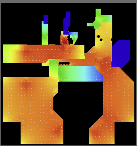
With the component substitutions I made for this board, this practice served me extremely well. Paired with using a thermal camera for PCB debugging, it makes tracking down issues on the board trivial.
First Issue: 3.3V Linear Regulator
When powering up the board the first time, I immediately had what looked like a short circuit. Never a great thing on first power up. This would have been very challenging to track down, but in under 30 seconds my thermal camera noticed that the linear regulator was the only component on the board heating up.
Taking a closer look at the component, and checking pinouts, I found my first mistake: I designed the board around the AP2114H regulator, and purchased the AP2114HA as a substitute, as the H was out of stock globally. Having a toddler sitting on my lap while ordering meant I didn’t check the datasheet, and notice the pinout was different between the H and HA - I had guessed (without checking) that the A was an automotive spec part. That guess was very wrong.
I updated the PCB to use the AP2114HA, so the published design is correct. Rather than ordering new circuit boards, I found a pin-compatible 3.3v regulator at a local supplier to populate my prototype boards with. While waiting for the new components to arrive, I pulled the 3.3V regulator from the board to continue testing. The regulator’s main purpose was to power the microcontroller which I had not yet added to the board, so testing could continue without the regulator.
Second Issue: Driver MOSFETs
When powering up the board again without the regulator mounted, I noticed all the MOSFETs rising in temperature design having no load connected. I had also substituted these parts, and unfortunately pins 1 and 4 were swapped, meaning the gate pin was sitting on a GND pad, and the source pin was bridging GND to the gate pad.
I couldn’t find a pin compatible MOSFET in stock, so it was time for some serious rework and bodge wires. The MOSFET is not getting pushed anywhere near its thermal or current limit, so I added 2mm wide kapton tape over pads 1 and 4. This reduces the MOSFET to two source pins instead of three, however the current density at the remaining pins will still be well within acceptable margins. The MOSFETs are a DFN package, which thankfully have a tiny amount of leg extending beyond the body for each pad.

This small leg allowed me to solder a 32ga wire to the gate pin, and connect it to the nearby diode. This would have been a relatively easy fix, however I only had silicone insulated wires at my desk. The silicone insulation is far wider than the copper inside, and a much wider diameter than a PVC insulated or enamel insulated wire. Nevertheless, with a bit of fiddly soldering the MOSFETs were all now correctly connected.
LED Driver Testing
After fixing the two issues, thankfully the board worked flawlessly on the LED panel. The neutral white driver, which is the highest power driver, calculated to 96.65% efficiency which is extremely high. I was hoping to get close to this with the design, but after measuring the input/output voltages and currents the results were better than expected! The measured efficiency of the driver was 96.76%.
While that is higher than calculated, the drive current was also a bit lower than calculated. It will likely be worth testing other current sense resistors to see if any additional brightness can be gained from the panel. That being said, the LED panel is utterly blinding thanks to the very high lumen per watt LEDs that are utilized on it. Even with the LEDs underdriven by a small amount, the panel visually appears to be brighter than commercially available panels which I’m aiming to replace, despite being half the wattage.

Thanks to the spectacular efficiency of the driver, the temperature of the driver is very satisfactory. The inductor is the highest temperature component on the board, reading 43.4C (111F) after reaching a steady state, with the PCB around each driver sitting at around 35.9C (96.6F). With the ambient temperature of 19.5C, the highest temperature point of the board has a temperature rise of 23.9C (75F). This is in open air, however it shows that even when placed in an enclosure there is little risk of the board overheating.
Final Thoughts
This was my first time using one of Diodes Inc LED drivers, and I was very impressed with their spreadsheet for calculating component values, losses and efficiencies. The basic suggested schematic for the driver can be improved with a couple of low cost components, resulting in a very robust LED driver that has exceptionally high efficiency. The final driver has very low voltage ripple, giving very consistent light output - perfect for reducing eye fatigue and creating zero flicker in video.
The component shortage is going to be around for a while, this project was hit particularly hard with the effects, despite selecting well stocked components at design time. When ordering components just a week after creating the design, a number of critical components had gone out of stock. Thankfully this project is not complex or things may have been much more difficult than they ended up being due to missing components.
Altium’s supply chain intelligence can help reduce risk when selecting components, even with the global component shortage. Ensure your prototype and production hardware stay on track - start a free trial of Altium Designer today!
About Author
Related Resources
Related Technical Documentation
Design to Release, Without the Friction
- Keep reviews tied to the right version
- Reduce handoff confusion and rework
- Spot sourcing and release risk earlier
- Work solo, share when needed
Get Started
Thank you, you are now subscribed to updates.