


Order Up! Finding Your Chef Voice in Mixed Voltage PCB Design


I was watching a cooking program on television the other day when I noticed how chefs always seem to be yelling whenever they need something or are demanding another kitchen staff to do something. It started to dawn on me how much of a mixture a kitchen has to be: there have to be all sorts of people who are both capable of being quiet and listening, and being loud and giving orders when something needs to get done. When you stop to consider all of the noises of flames going up, people walking around, and sizzling, it’s a wonder how people communicate at all.
I’m no Michelin chef, but I can always appreciate a good balancing act. Bringing together a seemingly dissonant crowd of staffers, and making them work together and produce incredible food is no small task. I know from my experience integrating electronics components of varying voltage levels in my designs that smooth integration is more of an art than just a simple task. Mixed voltage designing requires more considerations than simply connecting components together.
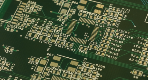
Mixed Voltage PCB Design: Low Voltage Integrated Circuits Or Voltage Translator?
As semiconductor technology advances, integrated circuits (IC) are able to operate at a lower voltage. A decade ago, microcontrollers operating on 3.3V began replacing those running on 5V. This means that now, logic and peripheral ICs are also shifting to lower voltages since a microcontroller can directly interface to ICs that are operating at the same voltage level.
It is natural to assume that the best option in design is to use 3.3V logic and peripheral ICs in the whole design. However, as is the case in most PCB design operations, there are always multiple priorities with each board: cost, efficiency, durability, and manufacturability. Lower voltage ICs are generally more expensive than conventional higher voltage ones; if the design involves a high number of logic ICs, then it may not be financially viable to opt for low voltage logic ICs.
If keeping the cost per PCB at a minimum is a concern, a voltage translator IC can be used to connect 3.3V MCU to 5V logic and peripheral ICs. Of course, this is only viable when the total cost of 3.3V ICs is higher than the cost of the voltage translator IC. While many of my more culinarily-inclined friends agree: you can always get away with more salt, this is the opposite of the case with voltage for ICs.
Don’t Have Too Many Hands in the Pot: Lower Signal To Noise Tolerance
I imagine a kitchen would be easier on a chef if they had a microphone, or a loudspeaker at all times. At least, they could save their throat from being yelled raw, but perhaps at the risk of irritating all of their staff. The same logic applies in electronics: the more people you can get to hear you, the more smooth your kitchen will run, or in digital signals, the margin of acceptable logic voltages is expressed by a percentage of the supply voltage. For example, a high logic signal is only validated when the input voltage exceeds 70% of the supply voltage. A 5V logic IC will require an input signal of at least 3.5V for a valid logic high while a 3.3V IC only needs 2.31V or above.
This means that the signal to noise tolerance is also getting lower with lower voltages logic ICs. This issue is even more prominent when analog signals are involved. When deployed in an electrically noisy environment, the signals are easily affected by interference and noise. This can sometimes trigger a false logic state for the system. When designing with lower voltage components, signal integrity is a critical issue and the best practices must always be obeyed. Simple techniques such as maintaining the right clearance and proper ground layout can be the difference between a defective product and a functional one.
Needs More Salt: Power Supply Module Design
When you are opting for lower voltage components, there are additional considerations regardless of whether you’re implementing a mixed voltage design or a pure low voltage design. When you’re having 5V and 3.3V components, you need to allocate voltage regulators for both voltage levels. This means power budget calculation need to be calculated for both regulators.
Besides that, you need to determine whether a linear regulator is sufficient or a switching regulator is the right choice. Every little decision made here could affect the complexity of the design and the overall cost of the finished product.
Furthermore, you should be wary of the additional heat dissipated when stepping down from 5V to 3.3V. While the voltage drop may seem minimal, an application that draws 500mA results in additional 0.85W of power loss. Depending on the type of regulator being used, this can be translated into a great amount of heat.
In order to keep track of voltage in your PCB design, the first step will always be to have immense comfort and confidence in your PCB design software. Having smart PCB software to keep a mixed voltage design organized will shave valuable time off your designs, and save you money in the future. When you need to access an easy-to-use PCB layout tool that includes everything needed to build high-quality manufacturable circuit boards, look no further than CircuitMaker. In addition to easy-to-use PCB design software, all CircuitMaker users have access to a personal workspace on the Altium 365 platform. You can upload and store your design data in the cloud, and you can easily view your projects via your web browser in a secure platform.
Start using CircuitMaker today and stay tuned for the new CircuitMaker Pro from Altium.
Related Resources
Related Technical Documentation
Table of Contents
Design to Release, Without the Friction
- Keep reviews tied to the right version
- Reduce handoff confusion and rework
- Spot sourcing and release risk earlier
- Work solo, share when needed
Get Started
Thank you, you are now subscribed to updates.

