Differential Signaling In High Speed Data Link Flexible Circuits

As noted in many previous articles, due to high-speed and high data-rate designs, most modern products utilize differential signaling. If utilizing the right design protocols and design toolsets, handling differential signaling in standard, rigid PCBs is easily doable. But utilizing differential signaling in flex circuits creates another set of issues, questions, and design challenges. This article will address how differential signaling is handled in flex circuits, including a high-level overview of the key aspects which need to be taken into account. It should be noted that there are many really, well-done write-ups on flex circuits that we’ve included in our design library (available through Speeding Edge). These write-ups include:
- “Comprehensive Analysis of Flexible Circuit Materials Performance in Frequency Time Domains,” authored by Glenn Oliver, Jim Nadolny, Deepukumar Nair presented at DesignCon in 2012.
- “Important Considerations for Flex/Rigid-Flex Designs” written by Anaya Vardya and David Lackey.
- “The Dos and Don’ts of Better Flexible Circuit Design,” by Mark Finstad.
- “Flex and Rigid Flex Guidelines” from EPECTEC.
The foregoing documents contain a vast array of information on flex circuit design, and for any in-depth design guidelines and issues, we refer our customers to them. In addition to these articles, I’ve also included the hands-on experience that Founder and President of Speeding Edge, Lee Ritchey, has gained in designing numerous flex circuits that contain differential signaling technology.
The Pluses and Minuses of Flex Circuit Technology
Implementing Differential Signals in Flex Circuits
At the onset, it’s important to understand that one of the key factors in implementing differential signals in flex circuits is that they are designed in the same manner as a surface microstrip transmission line. To review, a surface microstrip line is one of the four types of transmission lines found in PCBs, and it is created by etching one surface of a double-sided material. The top and sides of the line are exposed to air and referenced to a power or ground plane.
Some key characteristics of flex circuits are:
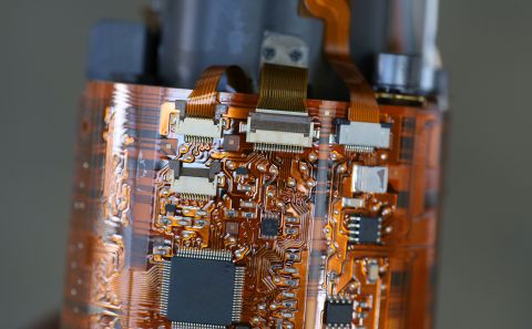
- They are hybrids of PCBs and round wires and they provide the benefits of each.
- They provide more options in packaging geometry over rigid PCBs.
- In those areas on a flex circuit where component mounting, support and durability are required, stiffeners are added to support the circuitry. These stiffeners typically range from .005” to .125”.
- Impedance is the single most important transmission line property in a flex circuit.
Types of Products That Have Flex Circuitry
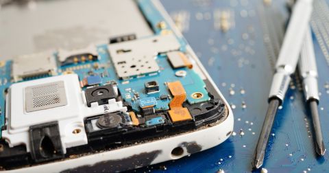
Lee Ritchey explains, “A flex circuit is a one- or two-layer board. It rarely goes beyond one or two layers because it stops being flexible. 95% of all flex circuits are one layer. If you open up a cell phone you will probably find eight or nine of them.”
“I would say 99% of flex circuits are in cell phones or inkjet printers and they’re all being built offshore. The flex circuits being built in the U.S. are for aerospace products.” (More about that below.)
Ritchey continues, “The challenge is ‘how do you achieve a 50-ohm impedance with a really thin dielectric?’ It’s really hard to etch narrow traces with a subtractive process which is how flex circuits are built virtually all the time.”
“The dielectric material typically used for flexible circuits is Kapton® (a polyimide) but it is a lossy dielectric,” Ritchey continues. “When I need to build low loss flex circuits I use an LCP (liquid crystal polymer) from Rogers.”
Any more there are a number of areas where differential signaling is used in flex circuits including HDMI, USB and PCI Express. Ritchey notes, “A few years ago, we worked on a design where we were using flex circuits for 5 Gb/S data rates. Successive design iterations have been almost four times that speed and the same circuit technology is still being used.”
He adds, “The reason for most flex circuits is to create a whole bus. You look at a parallel bus and it’s built using flex circuit technology. It’s cheaper to build a simple flex circuit if you have a lot of wires. That’s the real reason that flex rigid happens in aerospace. You get rid of cable bundles. I once built a product that had a backplane and coming up all four sides was a flex circuit with connectors on it going outside the box. The cards were slotted in parallel in the backplane. When we got rid of all the cable harnesses, I have to believe that the entire assembly weighed less. Getting rid of weight is always a significant benefit especially for aerospace technology.”
In the foregoing scenario, there was a combination of both flex and rigid circuits that had to be fabricated. Ritchey says, “It’s pretty complex and messy to manufacture both types of circuits at the same time. But, once you are done, there’s no cable, there’s no harnesses and you can stick in the board, bolt it down and you’re good to go.”
It’s important to note that the biggest failures that occur in avionics happen in those locations where cables meet connectors. Specifically, the solder connections deteriorate. Sometimes, this deterioration is due to repetitive use, while at other times it’s because the initial connections (strength of the bond) were not high quality.
Ritchey points out, ‘With all electronics, the failure almost always occurs in connections. Avionics products in particular are subject to shock and vibration and that’s what causes most connectors to fail. A wire will break where there is a contact between the connections. Anymore, when I see something fail, I start looking for the bad connection.”
The Important Factors to Consider
We don’t specifically address the flex circuit design process in our classes because it is a specialized design technique requiring a very specific set of skills. When asked about flex circuits in our classes, we refer our students to the four different documents listed at the beginning of this article.
However, there are some good, basic things to keep in mind when it comes to designing flex circuits and an overview of them is provided as follows.
- Don’t over-specify non-critical features on the drawing (or what is defined in the design spec).
- This does not help with the design being manufactured and it also adds cost.
- Don’t specify the adhesive thickness on the drawing.
- Only specify the overall thickness of the circuit and the overall thickness of the critical dielectrics that can impact impedance.
- Don’t add more tests to the circuit than needed. Extra tests add more cost.
- Talk with the circuit vendor before you specify the component pallet size needed.
The goal is to have the pallet be received in such a form that the components can be readily and efficiently handled and placed with pick and place equipment.
Design issues:
- Don’t put vias in a bending area. Many features put into a rigid or rigid flex board should not be used in flex circuits. These features can cause issues in the bending area and create discontinuities in the operation of the circuit.
- Don’t change conductor width or direction in a bend area.
- Don’t stack structures on multiple layers; this increases thickness and can create an I-Beam effect that is not desirable.
- Don’t use rigid flex construction if a multilayer flex circuit with stiffeners will do the job.
- Rigid flex can cost two or three times that of a comparable multilayer flex circuit.
- Don’t use sharp turns on the circuit border as sharp corners are prone to tears and once a tear is started, it can propagate.
Assembly issues:
- Don’t use a heat gun to form flex circuits. Heat guns can run at extreme temps that are beyond what a flex circuit can withstand.
- Don’t use rigid PCB temp profiles to reflow flex or rigid flex PCBs.
- Most flex structures are combinations of polyimide film layers and copper foil bonded together. This construction creates high moisture-absorbing properties and low tolerance to elevated temps.
- Don’t hesitate to reach out to a flex circuit manufacturer during the design process. They can provide a wealth of info along with good design advice.
Summary
As with all other electronic products, having a clear understanding of what can be achieved in a flex circuit will ensure that the product you design will be the product you receive. Differential signaling in flex circuits is achieved by designing them as surface microstrip transmission lines. With this approach, it’s possible to create high-speed, high data-rate flex circuits.
Flex circuit design is a unique skill set but there are several good sources of information available in published papers, articles and conference proceedings. In addition, flex circuit manufacturers can also be very helpful and provide guidelines that will enable you to achieve a good, working flex circuit design.
The design tools in Altium Designer® contain everything you need to keep up with new technology. Talk to us today and find out how we can enhance your next PCB Design.
