Rigid-Flex PCBs: Understanding the Pros, Cons, and Fabrication Considerations

Rigid-flex PCBs bring a lot of benefits to modern electronic design, starting with their unparalleled versatility. By combining rigid and flexible sections in a single board, they enable designers to achieve layouts that would be impossible with traditional PCBs. Whether it’s a wearable device that needs to fit into a small, curved enclosure or a high-reliability aerospace application requiring robust interconnections, rigid-flex PCBs provide an ideal solution. Beyond just saving space, they enhance reliability by eliminating connectors and reducing weight—making them a perfect choice for demanding industries. This combination of benefits makes rigid-flex PCBs an invaluable tool for solving complex design challenges.
However, diving into rigid-flex technology isn’t without its hurdles. To make the most of this approach, you need a clear understanding of both its advantages and its challenges, especially from a fabrication perspective. In this blog, we’ll walk through why rigid-flex PCBs might be the right choice for your project, explore some reasons you might opt for a different approach, and share essential design and fabrication tips to help you succeed.
Why Choose Rigid-Flex PCBs?
Let’s start with what makes rigid-flex PCBs so appealing. At their core, these boards allow you to combine rigid and flexible sections seamlessly. This capability opens the door to some remarkable design possibilities.
First, rigid-flex PCBs are fantastic for saving space. By eliminating the need for bulky connectors and cabling, these designs let you pack more functionality into smaller footprints. Think of wearable devices, where every millimeter counts, or aerospace systems, where weight savings can translate into significant performance benefits. The flexibility to fold or bend sections of the board gives designers the freedom to create compact assemblies that were previously impossible.
Reliability is another key selling point. Every connector or solder joint in a traditional assembly represents a potential failure point. By integrating rigid and flexible sections into a single structure, rigid-flex PCBs drastically reduce these vulnerabilities. This makes them an excellent choice for high-vibration environments like automotive systems or aerospace applications. Plus, fewer interconnects mean better signal integrity—a win for designs that demand precision and consistency.
And then there’s the mechanical flexibility. These boards are built to bend, twist, and flex while maintaining their electrical connections. Whether you’re designing for a robot that requires dynamic movement or a product with an unusual shape, rigid-flex PCBs provide the adaptability to make it work.
Why You Might Think Twice
As exciting as rigid-flex PCBs can be, they’re not a perfect fit for every project. There are some significant trade-offs to consider before committing to this technology.
Cost: For starters, the cost can be a dealbreaker. The materials used in rigid-flex PCBs, such as flexible substrates and specialized adhesives, are pricier than the standard materials used in rigid boards. Add to that the complexity of the fabrication process, with its precise lamination and drilling requirements, and you’re looking at a much higher production cost. Custom designs often need unique tooling and testing, which only adds to the expense.
Lead time: Time is another factor. Rigid-flex PCBs take longer to produce, partly because of the specialized processes involved and partly because not all manufacturers are equipped to handle them. If you’re working on a project with tight deadlines, the extended lead times could be a significant drawback.
Design: Combining rigid and flexible sections requires a higher level of expertise and meticulous planning. For example, you need to carefully consider how the stackup will handle thermal and mechanical stresses. Bend radii, transition zones, and layer alignment all need to be just right. A misstep in any of these areas can lead to issues like delamination or cracking—problems you definitely don’t want to encounter in production.
Do you need flex? And let’s not forget the risk of over-engineering. Not every project requires the capabilities of a rigid-flex PCB. If your design doesn’t need the flexibility or space-saving benefits, a traditional rigid board with connectors might be a more cost-effective solution. Sometimes, simpler really is better.

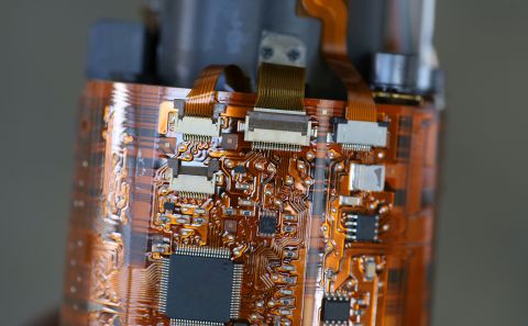
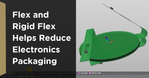
Flex PCBs help save space by forming to enclosure walls and holding components
Finally, while rigid-flex PCBs are durable, they’re not invincible. Continuous or extreme bending can shorten the lifespan of the flex sections. Similarly, in high-temperature environments, thermal expansion differences between the rigid and flexible layers can introduce stress, leading to potential failures. It’s essential to evaluate whether these limitations align with your application’s demands.
How to Get It Right: Fabrication Tips for Designers
If you’ve weighed the pros and cons and decided to move forward with rigid-flex technology, the next step is ensuring your design is ready for fabrication. Here are some key considerations to keep in mind.
First, material selection is critical. The flex materials you choose need to be compatible across both the rigid and flexible sections. Pay attention to properties like thermal expansion—you want the materials to expand and contract at similar rates to avoid delamination. Flexibility and durability are also important, especially for applications that involve repeated bending. And don’t overlook environmental factors. Will your PCB need to withstand high temperatures, moisture, or chemicals? Make sure your materials are up to the task.
Next, think carefully about the bend radius and transition zones. These are areas where rigid and flexible sections meet, and they’re often the weakest points in a design. To prevent issues, follow best practices for bend radius calculations. A good rule of thumb is to make the bend radius at least 10 times the thickness of the flexible layer. Additionally, consider reinforcing the transition areas with stiffeners or other supports to improve durability.

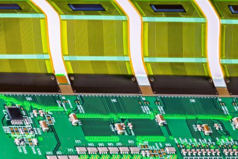
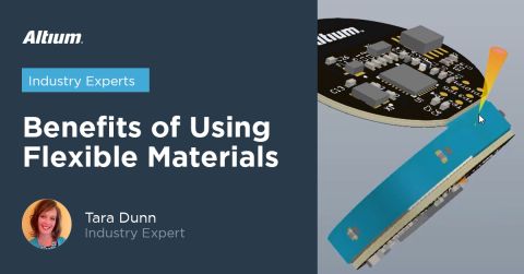
Flex PCBs are designed to have specific bending radius so that they can be statically or dynamically flexed
Design for manufacturability (DFM) should be a priority from the very beginning. Collaborate with your fabricator early in the process to align your design with their capabilities. This includes understanding their limits on things like trace widths, spacing, and layer counts. Simplifying your design where possible can also help optimize yield and reduce costs. For instance, avoid using excessive layer counts or overly tight tolerances unless absolutely necessary. Prototyping is another critical step—testing your design in a controlled environment allows you to identify and fix issues before moving to full production.
Bringing It All Together
Rigid-flex PCBs are a powerful tool for PCB designers, offering the chance to create innovative, reliable, and space-efficient designs. However, they’re not a universal solution. Understanding the trade-offs, from higher costs to longer lead times, is just as important as appreciating their advantages. By carefully evaluating your project’s needs and collaborating closely with your fabricator, you can harness the full potential of rigid-flex technology while avoiding common pitfalls.
Whether you’re designing for a wearable device, a high-performance aerospace system, or a dynamic robotic application, rigid-flex PCBs can provide the flexibility and reliability you need. Just remember: success starts with thoughtful planning, informed decision-making, and a commitment to getting the details right. With these principles in mind, you’ll be well on your way to delivering designs that push the boundaries of what’s possible.
