Alternatives to TEM Modes Transmission Lines

If you’re about my age or older, you probably remember being impressed with your old 14.4 kbps dialup internet. Those days seem long gone at this point as gigabit speeds are now commonplace. You can thank the advances by the signal integrity community and IC designers for getting us to this point. Still, one has to wonder whether current interconnect technologies are being pushed to their limits.
Data rates on PCB interconnects have increased significantly over the past several years, to the point where channelization and parallelization are required to push data rates into multiple hundreds of Gbaud per second. Multilevel signaling schemes (e.g., PAM4) over copper and equalization and compensation help get signals over longer links. Still, one has to wonder when we will hit the end of TEM mode transmission line usefulness. Here’s an overview of the current challenges involved in scaling to faster data rates per channel, and how alternative interconnect geometries may be the best way forward.
(Quasi) TEM Mode Transmission Lines
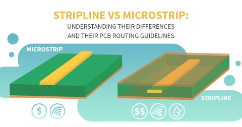
The most popular standard interconnects used in digital PCBs are definitely microstrips and striplines. Both are referred to as TEM mode transmission lines, although this is not exactly true for microstrips. In a microstrip line, the electromagnetic field distribution around the line is the best-called quasi-TEM as the microstrip is exposed to air on the top side. For a symmetric stripline, you have the closest approximation to a TEM mode distribution around the line.
You can only see true TEM behavior in a stripline under specific conditions. In real striplines and microstrips, you never have true TEM behavior, but you can often come close within a certain bandwidth. Whether a given transmission line is TEM, quasi-TEM, or has some other superposition of modes depends on a number of factors, as shown in the table below.
|
Microstrip |
Stripline |
|
|
Air above the line |
Signals see an “effective” Dk value, rather than simply the substrate’s Dk value. This skews the field distribution. |
Signals only see the substrate’s Dk value. As a result because the field distribution is trapped within the dielectric. |
|
Substrate Losses |
Microstrips are less affected by these losses. The tradeoff is they are more susceptible to crosstalk and external EMI. |
Striplines are more susceptible to substrate losses as the line is surrounded by a lossy medium. This produces some deviation from TEM. |
|
Dispersion (see below) |
True TEM behavior is only seen in dispersionless media. Microstrips see less severe (flatter) dispersion due to air above the line’s surface. |
More susceptible to dispersion as the line is surrounded on all sides by the substrate. |
|
Fiber weave |
PCBs substrates are not truly homogeneous or isotropic, which produces deviations from ideal TEM mode transmission line behavior. |
|
The goal of getting to higher data rates is to overcome signal distortion sources, such as losses and dispersion, seen by signals traveling on these high speed interconnects. This may require making use of some alternative transmission line geometries that can accommodate bandwidths extending to higher frequencies, which will be discussed below. As we’ll see shortly, the proposed solutions are waveguide geometries, each of which has its own mode structures and electric field distributions.
Technically, striplines and microstrips are not waveguides, although they do provide single-mode propagation (in the parlance of waveguides). Why does using a TEM mode transmission line really matter in a PCB? The answer is: it doesn’t, the conventional geometries normally used by the digital community just happen to be nearly TEM lines within the relevant signal bandwidths. Once a higher order mode is excited, you’ll find that propagation with a single-mode is critical in PCBs as only specific integrated circuits provide demultiplexing. Therefore, you must ensure single-mode propagation in order to preserve the shape of a signal.
Higher-order Transmission Line/Waveguide Modes
The important point to realize in the above discussion around striplines and microstrips is that there are no transverse modes around these transmission lines until you reach a very high frequency. Howard Johnson details this nicely, and you can calculate these higher order modes using standard wave equation techniques. This makes microstrips and striplines lossy waveguides as they have open geometries. You won’t see any higher order mode contribution until the half-wavelength of your signal is approximately equal to the transmission line’s distance to the reference plane.

Once you start working with waveguide geometries, you have an opportunity to overcome signal degradation problems in certain modes while also preserving single-mode propagation. The image below shows some waveguide structures that can be tailored for single-mode propagation at higher frequencies. The one exception is the parallel plate waveguide, which requires tailoring the exciting electromagnetic field distribution’s spatial distribution to match that of the desired transverse mode pattern.

You can read more about substrate integrated waveguides in one of my recent articles. Coplanar waveguide structures are widely covered, and I won’t repeat their characteristics here. One alternative to coplanar waveguides is mode-selective transmission lines, which I'll be covering in an upcoming article. There are some textbooks that provide beautiful analyses of parallel plate waveguides and fenced striplines; one such textbook is Electromagnetic Wave Theory for Boundary-Value Problems: An Advanced Course on Analytical Methods by Hyo J. Eom. Take a look at Yuriy Shlepnev’s DesignCon 2020 presentation for some excellent simulation results with these geometries.
When you’re working with new interconnect designs, you can design alternatives to TEM mode transmission line geometries with the powerful CAD tools in Altium Designer®. You’ll have the tools you need to route your designs and instantly check your layout against standard and custom design rules. The integrated electromagnetic field solver allows you to extract important parasitics and verify conformance to impedance constraints with standard transmission line geometries.
Now you can download a free trial of Altium Designer and learn more about the industry’s best layout, simulation, and production planning tools. Talk to an Altium expert today to learn more.


