


DC Block Filter Design


<p>Oscilloscopes are vital devices for hardware designers, allowing them to understand how the circuit behaves. It's very important to clearly understand the limits of your measurement equipment, including the probes, such as probe gain and bandwidth, channel input impedance, and maximum input voltage of the channel. For instance, most oscilloscopes only have an AC coupling option when using high-impedance input termination but not for <a href="https://resources.altium.com/p/mysterious-50-ohm-impedance-where-it-cam… Ohm</a>, where any DC bias exceeding the input voltage limit on your signal might completely damage the scope's input channel.</p>
<p>Simultaneously, you might still want to measure noise, transient response on a power distribution network, or high-speed sensor data with an unknown or high DC bias level, requiring you to use 50-Ohm input termination. Does that mean you cannot measure the signal at all? The answer would unsurprisingly be, "It depends". In those cases, a DC block filter must be used on the oscilloscope input to protect the channel from excessive DC bias voltage. This article will show you how to design, simulate, and validate a design you can build yourself.</p>
<h2><a id="dc-block-filter-for-oscilloscope-probes">DC Block Filter for Oscilloscope Probes</a></h2>
<p>Recent projects that I've been working on are related to power supplies, power distribution networks, and some very high-speed signals, and they require precise measurements for performance validation. Although using a high-end probe will help reduce adverse effects, I prefer directly attaching the board to the scope through a coaxial cable for critical signal measurement, removing any probe effects and bandwidth limitations from the equation. That being said, there is no adjustable attenuation factor anymore like many passive probes, making the scope's input channel vulnerable to over-voltage that exceeds the limit.</p>
<p class="text-align-center"><img height="436" src="https://lh7-us.googleusercontent.com/E-yScM0TJOkiYdlfd9ZvvDcOai2OdL2rOe…; width="602"></p>
<h3><a id="dc-filter-circuit">DC Filter Circuit</a></h3>
<p>Unfortunately, my oscilloscopes have a limitation of ±5V max when using the 50-Ohm input termination, meaning that I would damage the scope if I needed to measure noise or a signal with a DC bias over 5V. There are plenty of off-the-shelf DC block filters that can be purchased. However, that's not much fun. A DC block filter is just an RC high pass filter, with the 50-ohm termination in the scope being the resistor in the formula. Thus, we can build a simple and effective block filter with a single capacitor in series with the signal.</p>
<p class="text-align-center"><img height="275" src="https://lh7-us.googleusercontent.com/7ZnFuYTE5Sc36MMY1G4ClxzbcURjR8tT3b…; width="602"></p>
<p class="text-align-center"><img height="275" src="https://lh7-us.googleusercontent.com/Sz9DRfJnpcl-bXrworYJlX23aJWgzyzXjO…; width="602"></p>
<p>As you can see in the screenshots above, not too many components are needed for our DC block filter. A blocking capacitor (C1) is placed in series with the signal in the middle of the input and output. To give the board more potential future functionality, two additional 0402 pads on both sides of the blocking capacitor have been added, which will not be populated. Since there is no possibility to add pads into the manufactured PCB later on, providing that there is also enough board estate, it's always good practice to have some free pads for any required reworks or improvements as long as it doesn't affect mandatory functions and performance.</p>
<h3><a id="pcb-layout">PCB Layout</a></h3>
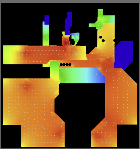
<p>Although it's a fairly simple board from a layout point of view, there are still some tweaks to make it perform better when considering signal integrity, especially when the target frequency of more than 6GHz is considered. It's important for the high-frequency – high-bandwidth signal to have as little disturbance as possible through the path, meaning that stubs and impedance discontinuities should be minimized. Due to this, the <a href="https://resources.altium.com/p/should-you-remove-ground-below-impedance… pad has been modified to be the same width as the 50-ohm track</a> while ensuring enough paste to hold the component in place securely.</p>
<p>Additionally, I've added a polygon cutout on a top layer under the conductor of the SMA connector to reduce the parasitic capacitance for a better impedance match. While we are on the subject, I've had previous issues with SMA connectors not fitting firmly to the board and having reliability problems as there is not enough solder if the pad is smaller, so I've preferred having a slightly larger pad. Eventually, it's just one of the engineering compromises a designer might face during the design lifecycle, but it's worth noting. As a final point regarding layout, plenty of stitching vias are added to increase the bonding of layers to ensure a flawless return path around the board and that no internal cavities bounce the energy around.</p>
<p class="text-align-center"><img height="295" src="https://lh7-us.googleusercontent.com/h52fQfm_HGCkuTuh9cKr5UbLEtNA166ltR…; width="534"> <img height="356" src="https://lh7-us.googleusercontent.com/mcs_k6rYlPl62SpTUYNiURfbr54Ph6iPSs…; width="646"></p>
<p class="text-align-center"><img height="333" src="https://lh7-us.googleusercontent.com/tdV8qnZZ4oz_ElQhNLJTxkBzBoLI34HPpB…; width="602"></p>
<p>Altium Designer has a fantastic feature I have loved from the first moment I started using it: panelization. It allows us to create customized panels by embedding one board into another as long as they share the same stack-up. Take a glance at the screenshots of my panels below. You'll quickly realize they're embedded at a 45-degree angle into the panel.</p>
<p class="text-align-center"><img height="344" src="https://lh7-us.googleusercontent.com/aWKcRpY46uhnmpRqdRxPiP0XQ20d_z9qIa…; width="621"></p>
<p>Standard FR4 dielectric, which is cost-effective and widely available in all fab houses worldwide, is a no-brainer for many of us; it's perfect for many applications. However, it's formed of woven fiberglass strands with epoxy filler, and these two materials' dielectric constants are very different. Having said that, although the dielectric constant variation is negligible for various designs, it becomes more critical when the rise time or bandwidth of the signal is high or even when an analog signal's wavelength is similar to the cavity size in the weave. Because of this, FR4 is not preferred for RF or very high-frequency boards; instead, a more homogenous material is selected, which is generally far more expensive.</p>
<p class="text-align-center"> <img height="354" src="https://lh7-us.googleusercontent.com/syBYpeaEQzqb-1QTmSpaYEHkKFhBtj9qbW…; width="640"></p>
<p>Despite this, I'm using standard FR4 for my DC block filter. I want the design to perform well past the maximum 6GHz bandwidth of my oscilloscope. It's not always possible to use non-standard dielectric for prototyping due to the cost or material availability. Therefore, zig-zag routing for critical signals or angled panel placement can be a quick workaround to reduce the fiber weave effect – it's just another engineering trade-off. Placing my boards on an angle will ensure uniform distribution of fiber bundles and resin through the transmission line for all boards, meaning that we don't end up with some boards having signals sitting on a fiber strand and others sitting on resin, resulting in different performance between boards.</p>
<h3><a id="circuit-simulation-and-component-testing">Circuit Simulation and Component Testing</a></h3>
<p>Theoretical calculations for the filter component values are a great starting point, and they will guide you through what to expect on the test equipment screen. It's always better to simulate to see the response, even though using ideal components may not always be as realistic. However, component-specific models and parasitic effects should be included. </p>
<p>We can use Altium's integrated simulation tools to estimate the filter's performance. We are looking for a high-pass response, and the cutoff frequency will tell us which frequencies would be attenuated by our DC block filter. The 30pF capacitor is selected to have a cutoff frequency of around 50MHz as per calculations, and the Altium simulation tool result shows this is the case. </p>
<p class="text-align-center"><img height="333" src="https://lh7-us.googleusercontent.com/3yAXywxM3TCcq_SjQ_eqqlyn7OqZkgSBPC…; width="602"> <img height="333" src="https://lh7-us.googleusercontent.com/icgxAyaiCZCdNy5ydAl4WyrUr_I67ymyXV…; width="604"></p>
<p>We all know very well that the real world has no ideal components. Unfortunately, all boards have parasitic capacitance and inductance. I'm using my Rohde & Schwarz LCX200 high-precision LCR meter to measure real-world parasitics of the board. I've soldered a couple of pin headers to the SMA connectors to easily fit the board in the through-hole fixture of my LCR meter. The LCX200 allows me to measure the capacitance between the conductor and ground in addition to the series capacitance, including parasitic effects, which are 5.8pF and 32pF, respectively.</p>
<p class="text-align-center"><img height="296" src="https://lh7-us.googleusercontent.com/dN8vwSpKpfsX50sqzF0MzJDObmnb-yp0HX…; width="537"></p>
<p class="text-align-center"><img height="327" src="https://lh7-us.googleusercontent.com/zhO8AiJ8yfUApQvl7z1_unnnp57dA1K7VU…; width="592"> <img height="329" src="https://lh7-us.googleusercontent.com/YAygno3z6yBv84PeJqCpFpT3WhftfW34Pr…; width="596"></p>
<p>Now, I can update the simulation to reflect the real-world board effects. Changing the series capacitor in the simulation to 32pF and then adding half the conductor-to-ground capacitance on either side of our blocking capacitor will result in roughly 54MHz of new realistic cutoff frequency.</p>
<p class="text-align-center"><img height="328" src="https://lh7-us.googleusercontent.com/bpkcVSBhX0Tg5-_keQn7LeueP0yuCmRSGE…; width="595"> <img height="328" src="https://lh7-us.googleusercontent.com/EkPUcK1fGFWB52WaHcWMpSuleBxHEhZrIt…; width="594"> </p>
<h2><a id="testing-the-circuit-board">Testing the Circuit Board</a></h2>
<p>After having some insights about expected results (Rule of Thumb #9 from Dr.Bogatin: Never perform a measurement or simulation without first anticipating the results you expect to see), it's time to test this board to validate the simulation and see the upper-frequency limit. A vector network analyzer is the right equipment for this board. I'm using a Rohde & Schwarz ZNB8 4-port VNA with a maximum frequency of 8.5 GHz. After calibrating the instrument, we can connect the DC block filter board with the cables we'll attach to the test board.</p>
<p class="text-align-center"><img height="333" src="https://lh7-us.googleusercontent.com/FtDQkaUbB7SFIpPwhkvriCDbM6yENSx7rO…; width="602"></p>
<p>Just after calibration, let's look at the cutoff frequency of the DC blocking filter. I added a marker to search for the -3dB point to the trace, and my VNA showed it's around 51MHz, which aligns well with the simulation. Any frequency less than 50MHz will be subject to a good amount of attenuation. Yet, it's important to verify that the pass-band area of this filter should be fairly transparent to the signal. I'm changing the start frequency to 75 Mhz and stop frequency to 8.5GHz to move the severe low-frequency attenuation area to the off-screen. Fortunately, there is no result for the -3dB point search, and we have a minimum peak at 7.6GHz, slightly above the -3dB point. That is a pretty satisfying result, and the loss in the range of frequencies I'm interested in will not impact my test results.</p>
<p class="text-align-center"><img height="321" src="https://lh7-us.googleusercontent.com/tlfbt5QdppxHALT8kU-lLnWpZK6cHo2f5-…; width="602"> </p>
<p class="text-align-center"><img height="321" src="https://lh7-us.googleusercontent.com/vOtTTcgEZ7L6SRMEuATfLsU-TtExuyGhzG…; width="602"></p>
<p>This board is open source under the MIT license; you can grab the <a href="https://github.com/issus" rel="noopener noreferrer" target="_blank">Altium project files on my GitHub</a> and build your boards at a fraction of the cost of buying a DC block filter. Use Altium's simulation tools to try out different capacitors to determine the right value for the cutoff frequency you need. I've also published a second version of this board, which has room for two series components, which is perfect if you also need to add attenuation to the signal or want to build a more complex filter.</p>
<p>A final note to keep in mind when designing your own filter is to use high-quality capacitors, ideally those intended for RF use, if you need a DC block filter that can go to high frequencies like mine. Another consideration is the blocking capacitors' voltage rating. These are only 0402-sized capacitors, so if you use larger capacitor values to reduce the blocking frequency, you'll soon find yourself with much lower voltage-rated capacitors.</p>
<p>Whether you need to build reliable power electronics or advanced digital systems, use the complete set of PCB design features and world-class CAD tools in <a href="https://www.altium.com/altium-designer">Altium Designer®</a>. To implement collaboration in today’s cross-disciplinary environment, innovative companies are using the<a href="https://www.altium365.com"> Altium 365™</a> platform to easily share design data and put projects into manufacturing.</p>
<p>We have only scratched the surface of what’s possible with Altium Designer on Altium 365. <a href="https://www.altium.com/altium-designer/free-trial">Start your free trial of Altium Designer + Altium 365 today</a>.</p>
About Author
Related Resources
Related Technical Documentation
Table of Contents
Design to Release, Without the Friction
- Keep reviews tied to the right version
- Reduce handoff confusion and rework
- Spot sourcing and release risk earlier
- Work solo, share when needed
Get Started
Thank you, you are now subscribed to updates.


