






EMI from Heatsinks and What You Can Do About It


While it may not be obvious, or while most designers may not think to check, heatsinks can generate EMI when they are connected to a switching element. This is a common problem in power supply design, and whenever a heatsink is placed in contact with a component that switches with high current draw at high frequency. Reducing EMI from heatsinks requires balancing the conducted and radiated portions, and there are some simple design steps you can take to do this.
EMI from Heatsinks and Parasitic Capacitance
When most designers consider choosing a heatsink for components on their board, it is likely they simply go with the manufacturer’s recommendations. They may use a heatsink with similar size as that recommended by the manufacturer, but made from a material with higher thermal conductivity. In some cases, designers might opt for active cooling measures, like a cooling fan, or (in extreme cases) liquid or evaporative cooling. All these courses of action are appropriate when using a standardized component, especially when the manufacturer provides the required heatsink and assembly guidelines.
Ever since CPU speeds reached 1 GHz and beyond, radiated and conducted EMI from heatsinks started to become more noticable, although this likely went unnoticed by many designers outside the power electronics and computer systems industries. Today, it is generally taken as gospel that the heatsink should simply be grounded, and that this will solve the problem of EMI. In reality, this does not completely eliminate the problem, and solving the problem requires managing parasitic capacitance.
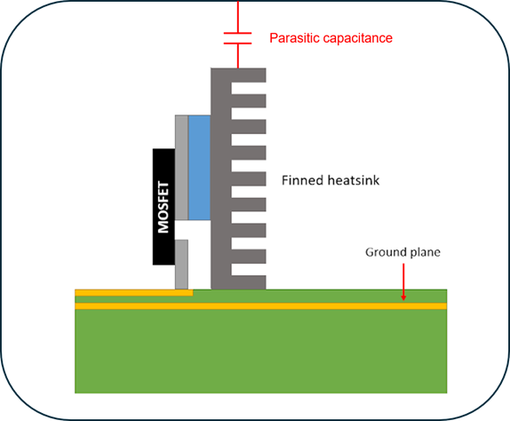
Both flavors of EMI arise due to parasitic capacitive coupling between a switching IC and the nearby heatsink. If you examine the structure of an integrated circuit with switching transistors, one can immediately see how the chip packaging and any thermal paste or interface material forms the insulating region in a capacitor. This parasitic capacitance is responsible for inducing a common-mode current in the heatsink.
Example with a vertical heatsink bonded to a MOSFET.
What happens next depends on whether or not the heatsink is grounded. If the heatsink is left ungrounded, then the heatsink and chip act like a source of radiated EMI, as there is no easy path back to ground for any capacitively coupled current. The current will excite multiple electromagnetic resonances in the heatsink, creating a set of regions in the heat sink with high current and strong radiation. This is one reason a heatsink is usually grounded by default. However, a strong current that is induced in the heatsink and diverted to ground can create a source of conducted EMI in nearby circuits, depending on the ground return path.
Why isn’t radiated or conducted EMI from heatsinks addressed more often? There are a number of reasons. Typically, EMI from a heatsinks becomes appreciable in two cases:
High current draw when switching. This is one issue in power electronics, wherein a bulky transistor switches in a large switching regulator. Switching to a higher voltage in a shorter time period generates a larger displacement current in the heatsink.
Fast switching in a processor. Processors that run faster can easily generate a large displacement current in the heatsink. They can also easily excite high frequency resonances in the heatsink.
In both cases, the capacitive coupling to the heatsink needs to be considered when designing a high voltage/current switching power supply. Other applications include VRMs for GPUs and CPUs, especially in devices that run at low voltage.
Balancing Conducted and Radiated EMI from Heatsinks
The usual solution is to simply ground the heat sink. This reduces the problem of radiated EMI by returning common-mode displacement current back to the reference plane. This requires using a heat sink with a conductive finish. If the heatsink is left floating, it will act like a large dipole antenna and can radiate strongly when a resonance is excited. As a switching digital component or MOSFET in a power supply has a broad signal spectrum, multiple resonances can be excited in a floating heatsink, producing a complicated radiation pattern.
One option to reduce radiated EMI from heatsinks is to simply use a smaller grounded heatsink. This can then be complemented with a small fan. However, using a fan brings about its own EMI issues, depending on where and how the fan is mounted. Another option is to use a grounded thermal washer between the heatsink and the component. The thermal washer is then bonded to the component and the heatsink with thermal paste on both sides. This effectively creates two capacitors in parallel, which reduces the total stray capacitance. Some commercially available heatsinks will contain this type a built-in thermal washer.
This odd-shaped heatsink has a unique resonance structure and can radiate at a variety of frequencies, especially when it receives a displacement current from a switching digital signal.
The thermal paste or TIM you use will play a role in determining stray capacitance. You should ideally use a TIM or paste with lower dielectric constant as this will further reduce the stray capacitance, no matter which method you use to reduce EMI.
Common-Mode Noise From a PCB Heatsink and Enclosure
As I discussed in another article in common-mode noise, the enclosure can also experience parasitic capacitance which allows current to start circulating as an unintended form of noise. The end result is typically common-mode noise on groups of conductors. If this noise stays on the PCB, it may not be an EMC problem although it may interfere with circuits. The bigger problem is the large current loop around the enclosure, which can radiate strongly and lead to emissions testing failure. However, if the common-mode noise in the PCB could arise on conductors which are routed to a cable, and the common-mode noise on the cable can also lead to conducted and radiated emissions failure.
In systems where there is a heatsink and an enclosure, there are two parasitic capacitances in series which will determine the impedance along the current loop circulating around the enclosure. This is drawn out in the image below.
In this image, the current path follows through the heatsink, into the enclosure, and back onto the PCB (the final step being direct conduction or via a parasitic capacitance). The common-mode noise created here sees an effective impedance formed only by the parasitic capacitance between the chip and the heatsink, or the enclosure and the PCB, whichever is smaller.
Note that this is not the only instance where a PCB experiences noise coupling from a switching circuit. Common-mode noise generated through the enclosure from MOSFETs is typically in the low-frequency range. Another common usage of heatsinks is on digital processors, and noise can also couple from the processor's heatsink into the enclosure; this portion of the path will have higher capacitance/low impedance compare to the MOSFET-to-heatsink path and the enclosure-to-PCB path.
So what is to be done about this common-mode noise? There are a few options:
- Change the geometry of the heatsink
- Change the location of the heatsink
- For connectors, place an EMI filter/choke near the connector
- For cabling, try placing a ferrite choke to handle low-frequency noise
In some cases, there will be a small amount of common-mode noise, but it may not have a major impact on emissions testing nor lead to failure. Pre-compliance testing is useful in these and many other situations as they can help you identify whether the board has a chance of passing conducted/radiated emissions testing. If you suspect the heatsink is responsible for the coupling illustrated here, try removing it and run another scan with your probe; if the emissions from the device reduce then coupling via the heatsink may be the culprit.
To learn more about some of the major challenges in testing, watch the Altium OnTrack podcast episode with Karen Burnham, an industry expert on a plethora of EMC standards.
The schematic design and PCB layout tools in Altium Designer® are ideal for defining a ground scheme for your heatsink in order to prevent EMI. You can then define grounding points or mounting holes in your layout, and you can include your heatsink as a mechanical object in your BOM automatically. You can also simulate various aspects of signal behavior with the post-layout simulation tools in Altium Designer.
Now you can download a free trial of Altium Designer and learn more about the industry’s best layout, simulation, and production planning tools. Talk to an Altium expert today to learn more.

About Author
Related Resources
Related Technical Documentation
Table of Contents
Solutions for Every Role and Team
- Discover and evaluate design options earlier
- Develop in one shared workspace
- Scale with control and compliance
- Connect every stage of hardware development
Learn More
Thank you, you are now subscribed to updates.