How to Optimize Your Design for Product Serviceability
Have you ever gone into a situation thinking that you’re totally prepared, only to come out of it feeling like you are totally clueless? Unfortunately, I have experienced this more times than I would like to recount. This was especially the case when I started designing products for serviceability or design for repair. There are many factors to consider before you decide whether your product should be designed for serviceability, and you should take the time to consider their feasibility. If the design for product serviceability and repair is your final decision then the bottom line is, you need to include features that make your product easy to service and troubleshoot. Since my initial design errors, I’ve learned how to optimize by design for product serviceability. Here are some helpful tips.
1. Add Visual Indicators
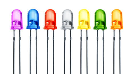
The servicing process for electronics on-site can be overwhelming for a support team, especially the malfunction is causing a delay in critical operations. Having a few well-placed visual indicators, like LEDs or LCDs, can help the support team quickly hone in on the problem. You can use LEDs to indicate that the board is being powered, that the microcontroller is alive, or that the board is properly transmitting and receiving data.
2. Label your PCB
Your tech support team can be armed with the latest schematics, but if you are not labeling onboard components properly then they will spend a lot of time hunting for the right part. Use a system to designate high-quality components according to their module and make sure that silkscreen labels are placed next to the right components. You’ll also want to add meaningful labels beside designators for wire to board connections. Labels like “PC” easily tell technicians that a particular connector is connected to a PC. You’ll also want to add polarity signs like “+” and “-” when incoming wire connections are polarity sensitive.
3. Implement Error Logging Capability
You can’t neglect error logging when you are designing complicated embedded systems. In most cases, problems and bugs that escaped lab testing are difficult to track on site. Those problems are often triggered by a combination of variables and cannot be reproduced easily. To make matters worse, the system may have been reset by the time the support team attends to the problem. At the very least, a basic error logging mechanism that involves nonvolatile memories like electrically erasable programmable read-only memory (EEPROM) or Flash should be incorporated into the design. An error code is definitely better than making a wild guess when troubleshooting a problem.
Instead of hunting for a hardware or software bug, log the error when it occurs.
4. Ease Of Firmware Update
While this is really the responsibility of the firmware engineer, it helps to know that leaving the debugging pins after the prototyping phase can help the design team to sometimes run diagnostic test code on site when that appears the best way to locate bugs or perform on the field firmware update. In a more elegant method, adding a microSD card circuitry can allow firmware upgrade by merely inserting a card with the latest version of the firmware.
5. Use Pluggable Connectors
Often the best way to identify a problem is to isolate and rule out other possibilities. When you have tens of digital inputs connected to a PCB and you’re not sure which are the problematic ones, you need to systematically test them. Pluggable connectors allow the support technician to quickly remove a connection, instead of wasting time in screwing and unscrewing every single wire.
6. Mount components on IC Socket
There is a reason why certain components like optocouplers and serial communications chips are still available in the plastic dual inline (PDIP) packages. For applications where your PCB is connected to wires that are exposed to lightning strikes, the first components that come into contact with those wires often suffer the brunt of the strike. This is why opting for PDIP packages and placing components on IC sockets could save you the time of dismantling components, desoldering and resoldering to replace the damaged components.
Use IC sockets for surge-prone components.
7. Ensure that your components are arranged properly
The proper component arrangement might seem intuitive to someone with experience, but it is good advice for less experienced engineers who are designing their first PCBs. This will help your technical support easily identify single components. Also, it is often a bad design practice to have your components strewn across your board. Remember to group connectors that belong to the same module together. For example, you’ll want to have all the connectors for optocoupler inputs together in a sequence followed by relay outputs. The same applies to place all the components for the power module in a section and not having one or two in the analog sections.
Are you looking to design a prototype or high-volume design that needs to be serviceable in the field? When you need to access an easy-to-use PCB layout tool that includes everything needed to build high-quality manufacturable circuit boards, look no further than CircuitMaker. In addition to easy-to-use PCB design software, all CircuitMaker users have access to a personal workspace on the Altium 365 platform. You can upload and store your design data in the cloud, and you can easily view your projects via your web browser in a secure platform.
Start using CircuitMaker today and stay tuned for the new CircuitMaker Pro from Altium.

