How to Setup and Interface with WS2812B LEDs
Are you in the mood for a good laugh? Well, I have a story for you. I’m a design engineer with decades of experience, but a LED project recently almost brought me to my knees in despair. I used to think that LEDs were as simple as getting the light emitting diode connected to a limiting resistor and a power supply. Aren’t they?
That’s exactly what went through my mind as I worked on an architecture model lighting project a couple of years ago. On this project the buildings and landscapes were powered by a WS2812B LED; a new and popular type of integrated LED at the time. However, unlike conventional LEDs, getting it to work is more complicated than turning on a power supply. This is because the LEDs interface with the microcontroller in a unique way. The communication interface between the microcontroller and the LED is a single wire, but unlike a standard UART serial interface, it is very time specific. Aside from appealing to us nerds who want to use a real-time processor to run their LEDs, WS2812B LEDs are useful for projects that require red, green, and blue (RGB) LEDs in large volumes. The WS2812B LEDs only have 3 connections, regardless of the number of LEDs in a strip, which avoids creating a mess of wiring.
How WS2812B differs from typical LEDs.
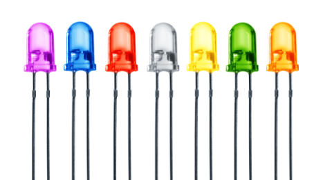
For us EEs, the word LED often conjures up a circuit symbol of a diode with a couple of arrows that indicate that it’s a light emitting diode. In electronics design, most engineers are familiar with dual pin LEDs that have anode and cathode connections. In embedded system designs, these LEDs are simple to control and are often used as visual indicators.
The WS2812B is a different beast than your typical LED. It is an RGB) LED that is integrated with an intelligent control chip in a single 5050 form factor. It supports a single line transmission protocol, where clocking and data signals are sent to the WS2812B, at a minimum 400 kbits per second, to control the RGB value of the LED. The WS2812B can be cascaded by connecting the ‘data out’ pin of one LED to the “data in” of the other.
This means that lighting up the WS2812B is not as simple as connecting a LED to a 5V DC power supply. If you try it, you’ll notice that nothing happens. To get a WS2812B LED to work you’ll need to send a valid command to the WS2812B LED from its controller. While it only takes a single command to change the color of the WS2812B LED, it is tricky to transmit the data packet. Since you’re working with a time-specific interface, the logic 0 and logic 1 commands are defined by their respective square pulse lengths. This tutorial gives a visual example of respective lengths of each pulse. Conversely, a conventional RGB LEDs simply requires a constant pulse width modulated (PWM) signal to sustain its brightness and color.
The need to modulate data parameters on a clock signal will stretch your coding ability and your understanding of the microcontroller to the limit. This gets even more convoluted when applied to multiple LEDs on a strip. To put things in perspective, a standard reel of WS2812B LEDs is usually 5 meters long with a total of 150 LEDs. In my experience, I ended up having to connect more than one reel of LEDs to a single point of control. So what’s the solution for controlling these fancy LEDs? To start, you’ll need the right LED controller.
Keys To Designing A Reliable WS2812B LED Controller
Designing a LED controller that functions properly is the key to driving a strip of WS2812B. Two major things to consider are that the WS2812B shares a single line for both clock and data, and that it supports a minimum data transmission rate of 400 kBits per second. This makes development tricky for both the hardware designer and the firmware developer.
Strips of WS2812B LEDs
Since the RGB parameters data are modulated within the clocking signal itself, precision is mandatory for the microcontroller (MCU) driving the LED. This leaves firmware developers with two choices. They can either select a high-end 32-bit microcontroller with immense processing power or opt for a low-budget 8-bit microcontroller. The 32-bit MCU will simplify firmware development but is significantly more expensive. Alternatively, the 8-bit MCU might not generate the WS2812B data packet accurately. Timing is key for these LEDs and a difference of approximately a microsecond could result in a different color. There is a way around this issue, you can write the LED driver in assembly language. That being said, be prepared for an expensive and complicated endeavor in firmware development.
In my experience, I opted for the 8-bit MCU. The one-time development cost was much better than paying for a 32-bit MCU for every single LED controller produced. Of course, that meant a tough upfront period of assembly programming. Either way, the choice is yours.
Once you’ve chosen your MCU, you’ll need to keep in mind that the WS2812B signal is sensitive to external interference. Any design mistakes can result in corrupted WS2812B data signals. Best practices like isolating WS2812B data from other high-speed signals and keeping traces short need to be followed diligently.
Knowing This Information About WS2812B Will Save You Unnecessary Problems.
Up until this point, it might seem like all you need to have a successful WS2812B based project is to have a functional LED microcontroller. Hang onto your hat, there’s more! On projects where multiple strips of WS2812B are connected, there are a few critical details that the technical team assembling the LED must be aware of.
One mistake will ruin your WS2812B project
The WS2812B LED strips draw high current and cause a voltage drop of 2.0V for 150 LEDs. This means that driving the LED requires a power supply with a sufficient current output, and to ensure a stable operating voltage the LED strips need to have a positive 5V-7V connection after every 150 LEDs. Without this, you can guarantee distorted LED colors and unhappy clients.
When strips of WS2812B are detached and manually wired, the soldering must be done with utmost precision as the data line is extremely sensitive to interference or dry-joint. A poorly connected WS2812B may result in the LEDs displaying random colors than what is transmitted. That’s the last thing you’ll want for your project.
Like it or not, the LED lighting industry is changing. Whether it is WS2812B or some other similar LEDs, you’ll want to keep in mind that it’s no longer about connecting LED strips to a power supply and hoping that it will work. It takes a team effort beyond the PCB designer to complete a project.
Are you ready to start designing your own WS2812B LED controller? Wondering how to route the high-speed WS2812B signal? When you need to access an easy-to-use PCB layout tool that includes everything needed to build high-quality manufacturable circuit boards, look no further than CircuitMaker. After you’ve determined your required PCB copper thickness and you’re planning for manufacturing, you can instantly generate the output files needed by PCB fabricators. All CircuitMaker users also have access to a personal workspace on the Altium 365 platform. You can upload and store your design data in the cloud, and you can easily view your projects via your web browser in a secure platform.
Start using CircuitMaker today and stay tuned for the new CircuitMaker Pro from Altium.

