Listen to the Baby: Use PCB LED Indicators and More for Serviceability
I’m a new dad and let me tell you: it is tough. I know everybody always tells you about the two sides of parenting, but I hadn’t really taken it to heart until now. That happy, sleeping, cuddly infant is around for about forty minutes after being fed, and then the crying begins. Sometimes, the problem is the milk temperature, sometimes a wet diaper, and sometimes because they feel like crying. In my years alive, I never anticipated being grateful for getting three straight hours of sleep in a night.
The part that’s so difficult about parenting, though, is that even when my child seems like a gremlin intent on making the most noise possible, they’re still the love of my life. Imagine if I could treat all of my PCBs that way after I’ve spent hours and hours bumping into critical design problems—unfortunately, my PCBs don’t cry when they have an issue. It might not seem like a huge standard, but an electronics PCB should be more effective in reporting faults or displaying the vital status of the system than my newborn. Much like that scrunched face right before the most ear-shattering scream you’ve ever heard, visual indicators are cheap and effective methods to enable your PCB to talk to you and help service teams maintain it.
Using LED as a Board Indicator for Serviceability
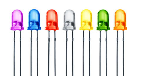
Light Emitting Diode (LED) is a basic electronics component that is to every hardware engineers. It is cheap and easy to interface with making LED the perfect visual indicator not only to the end user but for the service personnel as well.
When I’m in a design that involves a microcontroller, I’ve always included a heartbeat LED driven directly by the microcontroller output pin. As the name implies, the LED lights up at a regular interval to indicate that the microcontroller is well and running. If the heartbeat LED remained fully turned off or on, you’ll know immediately that something went wrong with the microcontroller.
Besides indicating the status of the microcontroller, LED can be used in various scenarios. For example, serial communication transmission can be visually highlighted by connecting LED to the transmitting and receiving connections. This allows the service technician to have a preliminary indication of the status of incoming and outgoing communication without resorting to sniffer tools or protocol analyzers.
You can also use LED to indicate the status of the power supply and the digital inputs. This saves the trouble of having to measure each point with multimeter during initial assessments. As LEDs are available in various colors, it is more systematic to use different colors for each type and purpose of indicators. If only I could make my newborn light up different colors for all the different needs and problems.
What’s That Look Mean? LCD Gives Smarter Fault Reporting
LED indicators fall short in providing detailed historical logs, despite how great they are for indicating system anomalies. That’s where a Liquid Crystal Display (LCD) is the better option to convey detailed information of faults and events to the service technicians. Of course, this requires the embedded system to have a dedicated non-volatile memory to store the logs.
A good embedded system will activate its Watchdog Timer (WDT) in the case of system crashes and recover by itself. If an LED is used, the service technician will miss out the fact that the system has suffered a crash. With an LCD, the service technician can easily browse through the logs for detailed information of the type and time of the faults.
One of the few drawbacks of designing with an LCD is that it can be expensive and complicated. Thankfully, there’s a design workaround. Instead of always adding an onboard LCD, incurring unnecessary costs and taking up valuable component space, I’ll allocate a connector for an external LCD carried by the service technician. This will enable simple alphanumeric character-based LCDs as visual indicators in designs without forcing unnecessary additional costs.
Don’t Forget to Sleep After You Use PCB Designators and Labels
It’s easy to get carried away with blinking lights and error codes. But some of the best visual indicators come in the form of PCB designators and labeling. In fact, a good hardware engineer will have serviceability in mind during the design process. Besides indicating the right components for the assembly process, PCB labels can help technicians in diagnosing for problems. PCB labeling can also ensure that technicians can properly identify various segments on the PCB for troubleshooting purposes. It is always helpful when various connectors are labeled according to their purposes and any polarity sensitive pins are clearly highlighted.
Adding labels and designators on a PCB is a simple process if you’re using smart PCB design software. When you need to access an easy-to-use PCB layout tool that includes everything needed to build high-quality manufacturable circuit boards, look no further than CircuitMaker. In addition to easy-to-use PCB design software, all CircuitMaker users have access to a personal workspace on the Altium 365 platform. You can upload and store your design data in the cloud, and you can easily view your projects via your web browser in a secure platform.
Start using CircuitMaker today and stay tuned for the new CircuitMaker Pro from Altium.


