New User's Guide to Defining a Library Methodology

When choosing a PCB library methodology, there is no universal solution for all users. While some small business users may require only the bare essentials, enterprise users may require a highly specific read-only representation with links to the supply chain.
Many different types of users in between may have yet entirely different requirements altogether. Consequently, there are several different library types and methodologies to meet this wide range of requirements. In this new user's guide to defining a library methodology, you will gain an understanding of the various library types and methodologies available so that they may make informed decisions when choosing and defining a library methodology.
INTRODUCTION TO DEFINING A LIBRARY METHODOLOGY
You may be introduced to many new library terms: integrated libraries, database libraries, and component libraries in addition to somewhat familiar-sounding schematic and PCB libraries. But what is the purpose of each one? Which library methodology is best for you? Considering Altium Vault-based component management, what happens to your investment in existing components? Starting at File > New > Library, deciding which approach to take with eagle managed libraries can suddenly become a process leading to more questions than answers.

Figure 1. Setting up a new library
It is important to first understand that there are a few different library methodologies to meet different user requirements. With just a brief overview of the various library methodologies and an explanation of each library type, the topic of libraries becomes easy to navigate and understand. From there you can decide which library methodology is best for you or your organization.
ESSENTIAL LIBRARIES
First, we’ll discuss the essential library types regardless of which overall library methodology you choose. Two primary library types, which are absolutely required at a minimum in order to create a PCB regardless of any specific library management scheme, are schematic libraries (*.SchLib) and Printed Circuit Board libraries (*.PcbLib).
A schematic library contains one or more schematic components that are graphically and electrically represented by a schematic symbol. Specific parametric information (such as the part number and component values), is typically added to each component and can be accessed during the generation of the bill of materials (BOM). One or more PCB footprints, as well as optional SPICE simulation (*.MDL or *.CKT files) and signal integrity (SI) (*.IBIS) models, are linked to the schematic component.
A Printed Circuit board library contains one or more PCB layout footprints that represent the physical pad arrangement and other mechanical attributes of the component. Optionally, solid model 3D information in the STEP format (*.STEP files) can be added to the footprint to represent the component’s physical shape in 3D mode.

Figure 2. Essential libraries - schematic and PCB
As the most basic methodology, these essential schematic symbols and PCB libraries can be used to manage components. In such a methodology, the schematic component represents the container for all possible views of the device (graphical symbol, electrical connections, solid model, SPICE mixed-signal simulation, and SI model). While this offers great simplicity and ultimate flexibility, this methodology does not really support strict enterprise-level requirements. Managing many separate files can be difficult, and increases the chances for library-related design errors.
INTEGRATED LIBRARIES
The next-level methodology incorporates what is known as an integrated library (*.IntLib). The concept of an integrated library is very simple: the exact same information used at the essential library level gets combined together to form a single read-only file representing an entire schematic library of many components.

Figure 3. Integrated library
The advantages of integrated libraries are many. Firstly, all linkages of the component to symbols, footprints, simulation, and SI models are permanent, so library-related design errors are minimized compared to just working with the separate essential library files. Second, an integrated library is read-only, so parameters or other attributes of the library cannot be inadvertently or easily modified. Integrated libraries cannot be directly modified, but are regenerated to support modifications. One of the most valuable benefits of the integrated library methodology is that the resulting single file representing an entire library is easy to distribute and manage.
DATABASE LIBRARIES
If access to parametric information stored in a corporate database is crucial for component management, then a database library (*.DBLib) should be considered. In a database library, components are managed as a set of database rows and columns. Each row in the database table begins with a key lookup identifier, which is typically a manufacturer part number or an internal corporate part number. The remaining column information defines each row as the component’s symbol, footprint, simulation model, SI model, and any number of additional parametric attributes.

Figure 4. Database library
The main advantage of a database library is access to a component’s parametric data from a common set of part information within an organization. This enables you to create a BOM with information accurately reflecting that used by the purchasing and accounting departments. Each unique component ID is a single orderable item from one or more suppliers. Mistakes of having the right schematic symbol, but the wrong component package is avoided. It is worth noting that database libraries access the required symbols and footprints from the essential schematic (*.SchLib) and PCB (*.PcbLib) libraries respectively.
The database library can be advanced one step further to an SVN database library (*.SVNDBLib) where the individual symbols and footprints can be managed under version control. This enables changes to individual symbols or footprints to be uniquely revisioned.
COMPONENT LIBRARIES
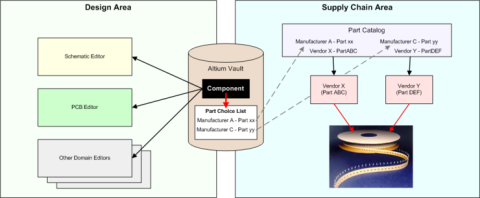
At the highest level of library component management, a component library (*.CmpLib), is used to associate all aspects (schematic capture, 2D/3D PCB layout, simulation, signal integrity) of a given component as an individual, revisioned item in a centrally accessible Vault.

Figure 5. The component library used to release components to a Vault
Under this modeling paradigm, the design component is separate from the manufacturer or supplier data. Such information is not defined as part of the component, but instead as a separate Vault item (a Part Choice List item) used to map a design component to one or more manufacturer parts. In turn, this can be mapped to one or more supplier parts, providing real-time supply chain information such as pricing and quantity available from each supplier.
In addition to real-time links to the supply chain, the vault enables strict control over authorized or approved components, item updates and revisions, and component lifecycle status.
LEGACY LIBRARIES
Some library formats are no longer or rarely used. For example, 3D models contained within a 3D (*.Pcb3D) library was at one time linked to the symbol to represent a component’s solid shape. Since the introduction of the current 3D implementation where STEP models are embedded within the PCB footprint, the 3D (*.Pcb3D) library is no longer used. However, this library format is still supported today for legacy purposes.
Eagle manages libraries for hardware description language (HDL) support exist for synthesis and simulation within the context of FPGA projects exclusively. Support for Verilog libraries (*.VERLIB) and VHDL (*.VHDLib) still exists, but are very rarely used anymore.
CONCLUSION
As a new user, you may find the numerous library types and terminology to be a daunting topic to fully comprehend at first. By classifying the main library methodologies by purpose, it becomes much easier to focus on the value and specific implementation details of each. By understanding this new user's guide to defining a library methodology, you will be able to make informed decisions on which library methodology is best for you or your organization’s needs.
