USB to Serial-Over-RJ45 Module

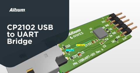
In a previous project article, I showed how to use the CP2102 from Silicon Labs (and the newer CP2109 by default) to build a USB to serial interface converter module that will plug directly into your computer through a USB A port. These modules can be readily purchased off of Amazon, but their reliability varies, so I added ESD protection everywhere I could on my custom module. In this article, I’m taking this project one step further and building another interface module specifically for networking equipment.
The module I will show in this article also converts to a USB interface to serial (UART), but data is delivered over a custom Ethernet cable and RJ45 connectors. You might wonder, why would someone use this type of module? Is it not advantageous to interface directly from serial to Ethernet?
Some networking equipment still uses a serial interface, but not all laptops offer such a port option, and not all servers will offer access to a switch or router over a configuration. However, a small USB module is a simple solution that allows interfacing directly to a networking unit over an Ethernet cable, but without establishing an Ethernet link.
To learn more you can watch our design tutorial on this topic, or keep reading to see how you can route a UART interface over RJ45.
UART Over RJ45 Overview
The reason for this project has to do with some of the data center electronics I have worked on in past projects. A lot of equipment, even newer equipment operating at slower speeds, still uses serial ports for communications via RS-232. However, they do not always use the typical D-subminiature connector, and most laptops today do not include such a connector. Instead, they might allocate an RJ45 for this interface so that the cable can be pulled into a standard cable bundle. The cable would then be secured in a terminal block on the other end until it is needed.
The module design shown below offers a simple way to interface with networking equipment over a laptop. The system topology is shown in the following block diagram:

The topology is pretty simple; we’re using the same topology in our CP2102 USB-to-UART bridge project, but with an additional component to drive signal over a cable through the RJ45 connector. The connector does not need Bob Smith termination due to the fact that it is not interfacing with an Ethernet PHY layer at a specified impedance.
Schematics
Take a look at the linked project above for the CP2102 circuit in the schematics. These closely follow the application note available from Silicon Labs. The other important circuit in this module is the line driver circuit, which is based on the SN75C3221PWR from Texas Instruments. There are other components that can perform the same function; in client projects on Ethernet switches we have used a similar part from Maxim Integrated.
The schematics for the line driver are shown below.

Although this component does include ESD protection built into its interfaces, I have added bidirectional TVS diodes on the data lines for maximum ESD protection; the same diodes were used on the USB interface and the original UART interface in the previous project. Note that these lines carry single-ended signals, so we could use unidirectional TVS diodes. The 1 kOhm resistor (R1) connected to pin 9 on the SN75C3221PWR is recommended from the datasheet, but if this component interferes with data transfer, it can be swapped with a 0 Ohm resistor.
PCB Layout
With this addition to the CP2102 circuit, we can look at the placement of the components in the PCB layout. The strategy here is to simply extend the board shape along the right direction to make room for the Ethernet connector and the SN75C3221PWR circuit. This allows most of the placements and some routing in the CP2102 circuit to be reused. The other circuits are placed to the right of the CP2102.

As can be seen, the CP2102 has been largely reused in its previous state. The RJ45 connector on the right side of the board is placed close to the TVS diodes (D4 and D5), but there is still enough distance leftover to provide routing beneath the SN75C3221PWR chip over to the connector.
One point I’d like to highlight in this board is the selection of the RJ45 connector. In this connector, the tab for releasing the attached cable is oriented vertically such that it can be pushed from the top side of the board. This is preferable to a bottom-side connector, where the tab would sit against the surface of the PCB.
Finally, the finished PCB layout is shown below. Here we do not have impedance-controlled routes between the SN75C3221PWR and the Ethernet connector, so we can route the outputs from the SN75C3221PWR essentially how we want. Note that this is all coplanar routing with GND pour on the top layer; this pour is then stitched back to the bottom GND layer with an array of stitching vias.

You can check the entire project in A365 Viewer:
If you would like to review this project, kindly click on the button below:

Whether you want to create simple interface converters or powerful networking equipment, you can design and build PCBs for your product using the complete set of design features in Altium Designer®. Once you’ve found parts and created your libraries, you can easily share data and release files to your manufacturer with the Altium 365™ platform.
We have only scratched the surface of what’s possible with Altium Designer on Altium 365. Start your free trial of Altium Designer + Altium 365 today.


