


When to Use a Rigid-Flex PCB vs. Multi-Board PCBs

At a Glance
Rigid-flex PCBs give an alternative to high layer count multi-board assemblies.


There are two popular ways to integrate multiple rigid boards into a complete system. One is to use multiple boards and connect them together with wires and cables, and the other is to use rigid-flex assemblies, where the flex sections are like built-in cables between rigid boards.
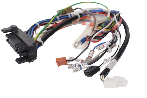
With rigid PCBs being the most common type of PCB, and fabrication capabilities and materials being readily accessible, simple rigid boards can be very cheap, especially when produced at volume. In some products, the mechanical constraints start to require multiple boards that then need to be linked together with connectors and cables, but at odd angles that can't be achieved with board-to-board connectors. They may also require a custom wiring harness to make electrical connections.
Rigid-flex boards are very convenient because they consolidate all of these different parts into a single assembly. You could conceivably consolidate a product with a dozen or more part numbers into a single part number for your PCB assembly. From that perspective, it sounds like rigid-flex is your best option, but what about the costs involved in producing these assemblies at scale?
If you have never looked into the manufacturing costs for these types of systems, we will try to put some numbers on these points so you can make the best decision for your product.
Simple PCB Cost Driver Comparison
Answering the above question can be quite difficult because getting an accurate cost comparison depends on many factors. Things like board materials, layer counts, feature sizes, component counts, and number of boards all play a factor in determining the total cost for a multi-board system. Additionally, not all rigid boards are the same; different boards in different fabrication regimes will have different slightly drivers determining the majority of the costs. These factors make it quite difficult to generalize a cost comparison.
That being said, we can still outline the major cost drivers for a rigid-flex assembly versus multiple rigid boards. I have summarized some of the biggest cost drivers in the following table.
|
Rigid |
Rigid-flex |
|
|
Tooling costs |
Tooling costs vary across board |
Flex section adds to total tooling costs |
|
Layer stacks |
Layer count reduction is possible with multiple rigid boards |
Hi layer count in flex region can dominate stackup costs |
|
Feature sizes |
Rigid boards can have finer HDI features that reduce layer count |
Flex PCBs need more specialized construction for advanced designs |
|
Reliability |
Rigid boards require greater fixation assistance on the enclosure |
Flex boards can be more reliable due to the elasticity of the flex ribbon |
|
Assembly |
Ridgid assembly has high throughput and high yield with most producers |
Assembly on flex is possible, but more components will require more rigid sections |
The above list contains just some of the major factors impacting total cost in the assembly you want to build. Many of the cost drivers in these boards come from the complexity of the layer stack build up, especially when you start to look at HDI on rigid or rigid-flex PCB assemblies.
From here, we can generalize a bit regarding some of these cost drivers in multi-board systems versus rigid Flex assemblies:
- Off the shelf cables for multi-board systems will cost less than a wiring harness
- A custom wiring harness will cost less than flex ribbon cables
- A flex ribbon cable will cost less than integrated flex layer in a rigid-flex PCB stackup
- A complex multi-layer flex PCB stackup drives up the cost of all rigid sections in a rigid-flex assembly
- Rigid multi-board assemblies offer more opportunities for cost reduction than flex assemblies
- HDI on rigid-flex with a polyamide core will always cost more than HDI on a rigid core
Cost Comparison Example
Suppose we have a system involving for pcbs that all need to be connected together with wires and cables. Let's suppose one of the boards is a higher layer count bored, while the others are simpler interface boards. For individual build of each PCB, we can write out the NRE and tooling costs as follows.
- Rigid PCB fabrication and assembly cost
- Board 1: 1800
- Board 2: 970
- Board 3 710
- Board for 465
- Connectors and cabling 33
- Rigid-flex PCB fabrication and assembly cost
- Flex layer fabrication: 1690
- Reduce all of the board costs by between 5 and 25%
There's a slight difference in the rigid section board cost due to process step reduction, but this gets lumped into the flex section cost. On a net basis, then increases the total cost for the system. We also have not included important points such as electrical testing, inspection to an IPC product class standard, or any other NRE charges. Because the flex is just another custom component in the entire assembly, it would increase these costs as well. Furthermore, assembly directly on the flex region can carry another cost increase compared to keeping everything on the rigid sections.
You Can Also Use Custom Cabling
Another wildcard here is the selection of cabling and connectors. Sometimes, it makes more sense to have a custom wire harness rather than off-the-shelf connectors and cables. You can also design a custom wire harness that interfaces with off-the-shelf connector receptacles on each board section. If you go this route, you then have to cost out the wire harness assembly for your rigid multi-board system.
When producing at volume, the assembly of a custom wire harness will not be much higher than the cost of off-the-shelf cables as the design cost is amortized across the production volume. Off-the-shelf or custom cabling will also cost less than a flex layer that links together your board sections. If the additional reliability of a flex region is worth the additional cost, then that is the approach that should be taken for the design. Wire harness tools in your ECAD software can give you a quick way to create these custom wire and cabling designs for use in your multi-board system.
Instead of using an external CAD tool to design wiring harnesses, use the complete set of wire harness and multi-board PCB design features in Altium Designer®. If you decide rigid-flex is the best path forward, Altium Designer's rigid-flex design features have set the standard for usability and excellence. When you’ve finished your design, and you want to release files to your manufacturer, the Altium 365™ platform makes it easy to collaborate and share your projects.
We have only scratched the surface of what’s possible with Altium Designer on Altium 365. Start your free trial of Altium Designer + Altium 365 today.
About Author
Related Resources
Related Technical Documentation
Table of Contents
Design to Release, Without the Friction
- Keep reviews tied to the right version
- Reduce handoff confusion and rework
- Spot sourcing and release risk earlier
- Work solo, share when needed
Get Started
Thank you, you are now subscribed to updates.

