

When UI.ModernDesignReusePanel is in the Public state - update the blue box below with the source code of the 'Open Beta Feature Moves to Public' snippet. The Design Reuse panel that is used to manage reuse blocks and described on this page is in Open Beta and available when the UI.ModernDesignReusePanel option is enabled in the Advanced Settings dialog. When this option is disabled, the previous…
Parent page: Design Panels Reference Workspace panels are essential elements of the Altium Designer environment. Whether specific to a particular document editor, or used on a more global, system-wide level, they present information and controls that aid productivity and allow you to design more efficiently. Accessing Panels When Altium Designer is first started, a number of panels will already…
Altium Designer combines a myriad of features and functionality, including: Advanced routing technology Support for cutting-edge rigid-flex board design Powerful data management tools ECAD Libraries containing over 300,000 ready-to-use components Powerful design reuse tools Real-time cost estimation and tracking Dynamic supply chain intelligence Native 3D visualizations and clearance checking…
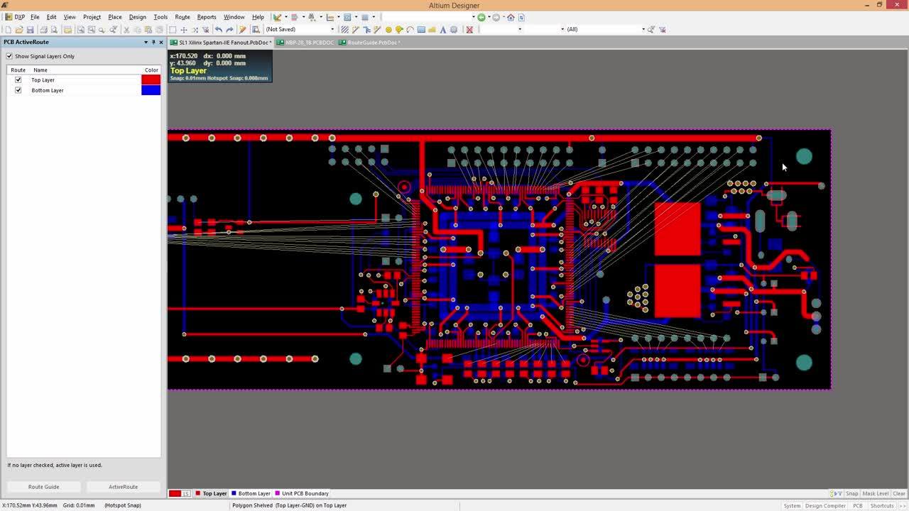
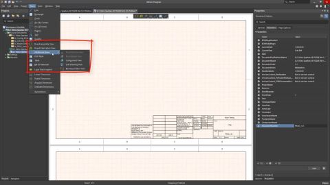
When working with a graphical document, such as a schematic sheet, PCB document, or Draftsman document, you can zoom and pan the document to focus on a specific document area. The basic shortcuts that can be used to do this are: Ctrl+Mouse Wheel to zoom in and out Right-Click, Hold&Drag to slide the document around The View main menu includes a number of commands that can be used to control the…
Supported MCAD Software The following MCAD platforms and versions are currently supported: Autodesk Inventor Professional® Autodesk Fusion® (Microsoft Windows version only. Autodesk Fusion Personal license only supported by Altium CircuitMaker) Dassault Systemes SOLIDWORKS® (Standard, Pro & Premium) PTC Creo Parametric® Siemens® NX™ - (for designers with an Altium Enterprise Solution) Onshape®…
Bridging the ECAD-MCAD Divide The electronic product you hold in your hand is the melding of numerous, independent designs. Firstly there's the enclosure you're holding; inside that, there will be one or more electronic circuit boards, and on the board, there is often a microprocessor running software. Beyond that, there can be specialized sections of circuitry to perform unusual sensing or…
The design rules of the Manufacturing category are described below. The Manufacturing category of design rules. Done - 26.6, at Beta release: disable Beta and Altium employee for the conditional box above, enable Beta and Altium employee for the conditional box below. 26.10, at the Public release (PCB.Rules.RuleSets is out of Closed Beta): delete the conditional box and the content above, remove…
Altium CoDesigner is an interface for transferring printed circuit board designs between the ECAD and MCAD design domains. Design changes are passed through an Altium Workspace, which acts as a bridge between the ECAD and MCAD domains. Altium MCAD CoDesigner works with Onshape, a fully cloud-native computer-aided design (CAD) and product data management (PDM) platform. To CoDesign between Altium…
Parent page: Global Sharing In support of Altium 365's Global Sharing paradigm, Altium Designer supports the ability to share your design projects with others, anywhere around the world, directly from within the software. This complements the ability to share designs from within the browser-based Altium 365 platform itself. The following levels of sharing are supported from within Altium Designer…
Parent page: Finalizing the Board Design Via stitching is a technique used to tie together larger copper areas on different layers, in effect creating a strong vertical connection through the board structure, helping maintain a low impedance and short return loops. Via stitching can also be used to tie areas of copper that might otherwise be isolated from their net, to that net. In RF designs, to…
Learn More