All About Box Build Assemblies

When you’re ready to manufacture a new device at production volume, there are many aspects of the product that must come together. The enclosure, cabling and connectors, embedded software/firmware, and of course the PCBA all have to be considered in totality. There is a quick way to get your product into a usable enclosure, complete with input power and cabling, and with a form factor that fits your PCBA. This overused route to a new product is a box build assembly.
I’ve talked to many designers and product developers, and many of them have never produced a new product with their CM as a box build. Sometimes known as systems integration, box builds essentially aggregate all the important elements that would appear in a finished product into a simple assembly. They may not have the aesthetic you would expect from some of the most popular consumer products, but they are an effective option for expedited production.
Anatomy of an Electronics Box Build
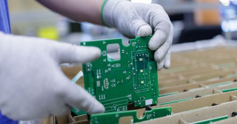
Some manufacturers will offer box build services, where they bring many of a system together into a single package and ship you a ready-to-use assembly. The PCBA, its cabling and mounting, and the box itself are all assembled into a single enclosure that functions as the product’s packaging. The enclosure itself could be an off-the-shelf enclosure, a sheet metal enclosure, or even a 3D printed box.
Some of the steps involved in manufacturing a box build assembly might include:
- Installation of the PCBA (or multiple boards) into the enclosure
- Machining a simple enclosure, usually from sheet metal, or adapting an off-the-shelf plastic/metal enclosure
- Machining any holes or openings into the enclosure for cables and harnesses
- Flashing of firmware/software into the main PCBA memory if components are not supplied pre-flashed
- Installation of any switches, buttons, screens, or other HMI elements
- Functional testing, typically involving a customer-supplied fixture and automated test program

The idea is for the customer to be able to use the assembly as soon as it’s received. To ensure you can quickly take your box build and take the product to market, the build will still have to go through the same qualifications as any other electronic device sold on the open market. For example, the device will need to pass FCC/CISPR EMC compliance testing at minimum, and another consumer or commercial standard (UL, IEC, etc.) might apply to your product.
This portion of the process is best completed during the prototyping phase. Because the enclosure plays an important role in things like EMC and user safety, a complete box built should be assembled and tested for compliance, it is not just the board that will need to be qualified.
What You Need for Box Build Assembly
First and foremost, you need to find a contract manufacturer that can support your needs in your box build. Your contract manufacturer should be able to qualify any custom enclosure design and develop an assembly process for the build. The assembly process should include all the relevant steps for mechanical assembly, as well as testing, inspection, and quality control.
As you work through the build process with your manufacturer’s engineering team, you’ll be able to identify mechanicals, harnesses, and cabling options that will match your requirements, and you can incorporate these points into your design. It’s best to complete these tasks early because they can constrain the PCB layout and design in terms of component placement around the board, and these points will influence what the manufacturer can do to accommodate your box build.
What Documentation is Needed For a Box Build?
All of the standard documentation you would generate for a standard fabrication run will be needed for a box build assembly. The basic set of files (Gerbers/ODB++, BOM, drill files, etc.) will be needed for the PCB, but this set of files won’t help with the rest of the box build.
To ensure your enclosure, connector placement, mounting, cable, and harness requirements are understood by your assembly house, it’s a good idea to prepare a mechanical drawing. The best case would be a STEP file with a simple enclosure model that outlines your desired box form factor. Even a simple drawing is better than nothing as it will give your manufacturer a better idea of the product you expect to receive from a box build.
Finally, the BOM for the PCBA will need to include any mechanical components and cables/harnesses required for the box build assembly. This can include, but is not limited to, nuts, screws, bolts, wiring (including gauge), standoffs, cables, harnesses, and information about the enclosure. If you’re leaving these details up to your manufacturer, ask them to update your BOM with any additional parts they will use in the final assembly.
The next time you want to generate your manufacturing documentation for a box build, use the complete set of product design tools in Altium Designer®. The Draftsman utility expedites creation of fabrication and assembly drawings, and the OutJob file feature can quickly generate the main set of deliverables for PCB manufacturing. When you’ve finished your design, and you want to release files to your manufacturer, the Altium 365™ platform makes it easy to collaborate and share your projects.
We have only scratched the surface of what’s possible with Altium Designer on Altium 365. Start your free trial of Altium Designer + Altium 365 today.

