


How ECAD-MCAD Co-Design Supports Aerospace Reliability and Compliance

At a Glance
Aerospace designs demand precision. Discover how ECAD-MCAD co-design reduces costly errors and accelerates compliance for mission-critical systems.


In aerospace, the margin for error is razor-thin. A misaligned connector or overlooked clearance can mean millions in redesign costs, months of certification delay, or worse, a system failure in the field. Regulatory bodies like the FAA (DO-254) and defense standards such as MIL-STD-810 exist to minimize these risks, but compliance is only as strong as the design process itself. Increasingly, aerospace companies are embracing ECAD-MCAD co-design as part of a broader digital thread strategy to ensure reliability, traceability, and first-pass success.
Challenges of Siloed ECAD and MCAD Design in Aerospace
Traditionally, PCB designers and mechanical engineers have worked in silos, trading static STEP, IDF, and DXF files back and forth. The result is a workflow riddled with blind spots and data quality issues.
From my own experience, DXF files can be imported with geometries that aren’t fully closed or come in with offsets that go unnoticed until much later, sometimes not until parts are manufactured and suddenly don’t fit.
STEP files often export with incorrect shapes as well, introducing dangerous inaccuracies into the mechanical model. Even when the files are usable, the process is slow and error-prone.
Engineers in online forums often echo the same frustrations:
- Translations that “never quite line up”
- Wasted hours re-importing data
- Constant uncertainty about which version is current
The fragmented approach creates inefficiency and undermines reliability.
Aerospace systems are expected to perform flawlessly under extreme conditions, yet every geometry error, misaligned component, or missed update increases the risk of mechanical failure or compliance violations. Without a unified, accurate design process, true reliability becomes almost impossible to guarantee.
Mechanical engineers in particular face several pain points with this fragmented workflow:
- Inaccurate or Out-of-Date PCB Models: When board designs are handed off via static files, the mechanical team may end up working with outdated board geometry. If the PCB shape or component layout changes and the MCAD model isn’t updated in real-time, it can result in misaligned mounting points or enclosure fits that fail validation.
- File Conversion Bottlenecks: File-based workflows also suffer from unpredictable behavior when importing into MCAD tools. Sometimes the geometry comes in, but the placement is shifted or misaligned.
- Misaligned Geometry and Constraints: Without a unified view of the product, it’s easy for mechanical constraints to be violated inadvertently. For example, a connector on the PCB might collide with the enclosure because the ECAD and MCAD models weren’t synchronized. Such geometry misalignments cause fit issues but can also compromise reliability (e.g., a board that flexes or vibrates because of improper support). Each misalignment discovered late in the process triggers redesigns and additional verification cycles. NASA shows that a 10% schedule slip leads to about a 12% cost growth in the program. This is how mistakes in the data imports can be costly.
- Lack of Traceability Between Domains: Siloed workflows make it difficult to trace design decisions and changes across electrical and mechanical domains. If an auditor asks how a particular clearance or component placement was determined, teams must dig through separate ECAD and MCAD records to piece together the history. The fragmented traceability can slow down certification audits for standards like DO-254, which require clear evidence linking requirements to implementation.
Working in disconnected tools makes it challenging to ensure that all elements of an aerospace design remain in lockstep with each other and with regulatory requirements. Miscommunications or late design changes can lead to scenarios where a system fails a compliance test (for instance, a PCB assembly might not withstand a vibration test per MIL-STD-810 due to an unforeseen mechanical resonance). Clearly, a more integrated approach is needed to avoid these pitfalls.
Real-Time ECAD-MCAD Co-Design: Minimizing Errors and Compliance Risks
The solution to these challenges is real-time ECAD-MCAD co-design, a collaborative design approach where electrical and mechanical engineers work from a shared source of truth. Instead of tossing design files over the wall, both teams can see and contribute to a unified 3D model of the PCB and its enclosure. Changes in one domain are instantly communicated to the other, drastically reducing the chance of errors or surprises.
By adopting an ECAD-MCAD co-design workflow, aerospace design teams can:
- Catch Issues Early: With a synchronized 3D design view, misalignments or interferences become apparent immediately. Engineers can perform fit checks and even run preliminary simulations (for stress, thermal, or vibration) on the up-to-date model, catching problems that would otherwise surface during prototyping. Early detection of electro-mechanical issues prevents costly late-stage rework.
- Reduce Design Iterations and Delays: Real-time collaboration means fewer back-and-forth file exchanges and fewer iterative loops. Changes are applied directly to the unified model, so the team spends less time waiting on exports/imports and more time engineering. This streamlines review cycles. A change that would have taken days of ping-ponging files can be reviewed and approved within hours. The net result is a shorter design cycle with minimal bottlenecks.
- Improve Compliance Confidence: When the ECAD and MCAD designs are always in sync, there’s less risk of a last-minute discovery that a design violates a requirement. Teams can continuously verify that form factor constraints, clearance requirements, and other compliance-related design rules are met in the 3D model. Continuous verification builds confidence that by the time the design is finalized, it will pass regulatory checks the first time. Moreover, a co-design platform often logs all changes in one place, creating an audit trail that simplifies demonstrating traceability for standards compliance.
- Enhance Cross-Team Communication: Co-design breaks down the wall between disciplines. Mechanical and electrical engineers can discuss design changes with full context, looking at the same digital model. This shared understanding fosters better communication. Decisions are made collaboratively with awareness of both electronic functionality and mechanical integrity. The improved communication reduces misunderstandings that could otherwise lead to errors or design oversights.
In essence, ECAD-MCAD co-design aligns the mechanical and electrical aspects of the project into one cohesive process. For aerospace projects where failure is not an option, this approach helps ensure that nothing falls through the cracks. But how can teams implement such a workflow effectively? This is where modern co-design tools come into play.
How Can Teams Bridge the ECAD-MCAD Gap?
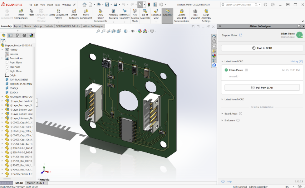
Altium’s MCAD co-design is a solution purpose-built to connect PCB designers and mechanical engineers in real time. It bridges Altium Designer (ECAD) with popular 3D MCAD platforms (like Dassault SOLIDWORKS®, PTC Creo®, Autodesk Inventor®, Siemens NX™) through a smooth, bi-directional link. With MCAD co-design, the two domains effectively operate on a shared design, without forcing anyone to leave their preferred software environment.
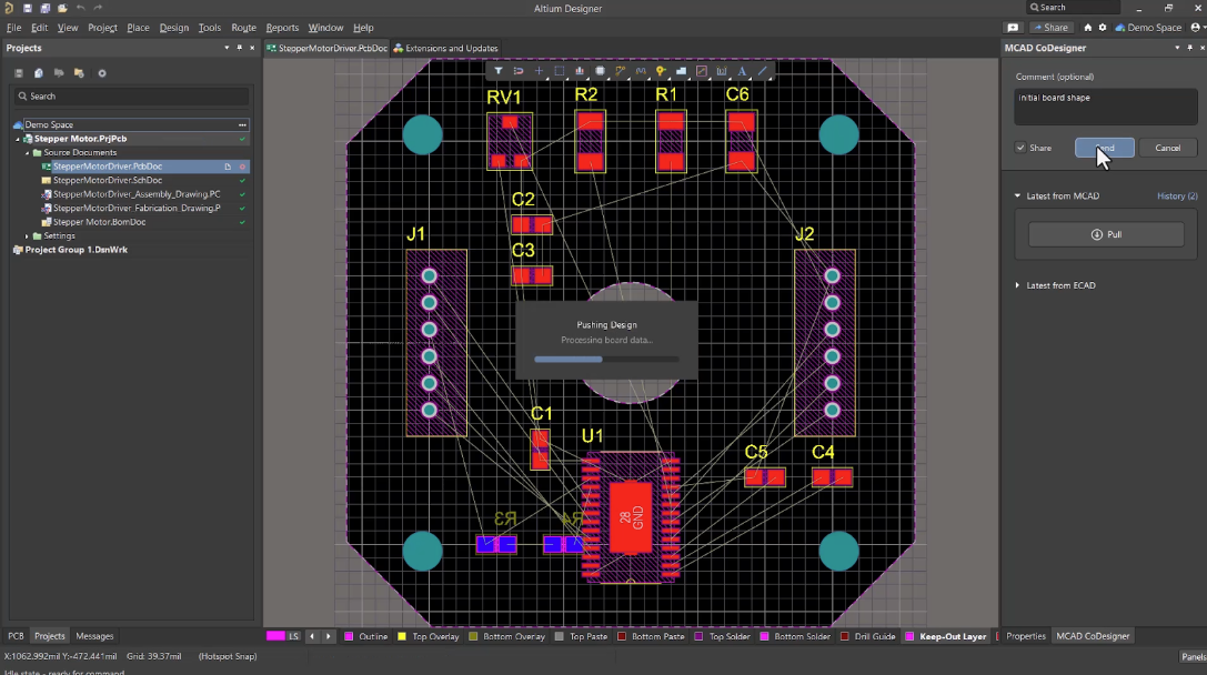
Instead of relying on intermediate file formats, Altium’s co-design enables direct synchronization of design data. A PCB engineer can push board updates (board shape, component placements, keepouts, etc.) to the mechanical engineer, who sees those changes inside their MCAD tool as soon as they sync.
Likewise, if the mechanical engineer adjusts the enclosure or board placement, they can push those changes back, and the PCB design in Altium updates automatically.
This push-pull workflow eliminates the need for exporting STEP or DXF files for every little change. There’s no longer a need to spend hours exporting and importing files. All ECAD-MCAD data is translated and transferred automatically.
Crucially, MCAD co-design maintains the accuracy and integrity of design data between tools. It preserves native geometries and constraints, so that critical features like mounting hole alignments, board outline dimensions, and component keep-out zones remain consistent in both ECAD and MCAD views.
For example, if a mechanical designer defines a keep-out region in the 3D model (perhaps to ensure a tall component doesn’t interfere with a chassis rib), that constraint can be pushed to the PCB layout, where the electrical designer sees it and cannot place components in violation. This tight integration means that by the time a design is complete, the mechanical form and the electronic function fit together perfectly, a necessity for high-reliability aerospace assemblies.
The integration with MCAD tools also allows mechanical engineers to perform advanced analysis on the electronics assembly using accurate data. They can use the exact PCB geometry and even copper features transferred from Altium to run simulations like thermal analysis or vibration FEA on the board within the context of the full system. Such analyses are critical for complying with standards like MIL-STD-810 (which might require demonstrating that the design tolerates shock and vibration). With co-design, these simulations can happen earlier and with greater fidelity, because the mechanical model of the PCB is always up-to-date.
Improved Collaboration, Review Cycles, and Traceability
By unifying ECAD and MCAD design, Altium dramatically improves team collaboration and shortens design review cycles. Both engineers are effectively working on the same digital model, so design reviews become much more about real-time discussion rather than document exchange. Stakeholders can rotate a 3D model of the board inside its enclosure and verify together that every component, connector, and fastener is where it should be. This reduces the iteration loops needed to get approval from both mechanical and electrical leads.
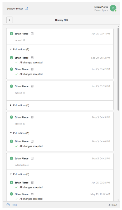
Another benefit is the built-in change tracking and version control that a platform like Altium provides. MCAD co-design keeps a history of changes. When an engineer pushes an update, the other side sees exactly what changed and can even accept or reject the change with comments. Every adjustment is logged, and decisions are documented in context. Come audit time, the team can easily retrieve a history of design changes and the reasoning behind them, which is invaluable for showing compliance with design control processes (as required by DO-254 and similar standards). The days of scrambling through email threads and disparate file versions to explain a design decision are gone. Co-design builds that traceability into the workflow.

In practical terms, having this level of coordination means fewer prototypes and physical re-spins as well. When electrical and mechanical designs stay synchronized, the first article manufactured is much more likely to meet all requirements. Companies have reported significant reductions in design spins by adopting concurrent ECAD-MCAD design practices. Less rework and fewer prototype cycles not only save time and cost but also translate to a smoother path through qualification testing and certification.
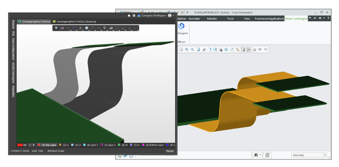
Example: Rigid-Flex PCB in an Avionics Enclosure
Consider a hypothetical avionics device that uses a rigid-flex PCB to fit within a tight enclosure. The flex section of the board must bend around an interior corner, and multiple connectors on the rigid sections must mate with chassis interfaces at precise locations.
In a siloed process, the mechanical engineer might specify an initial board outline and connector positions, but as the PCB layout is routed, the electrical engineer might need to adjust component placements or add a flex bend that wasn’t anticipated early on. If those changes aren’t immediately communicated to MCAD, the 3D fit could be compromised.
By using ECAD-MCAD co-design, the team can collaborate on the rigid-flex design in real time. As soon as the PCB designer adjusts the flex bend radius or repositions a connector on the board, the mechanical model updates to reflect the new geometry. This allows the mechanical engineer to verify that the flex circuit can be assembled without strain and that connectors still align with the enclosure openings. Rigid-flex designs especially benefit from co-design because the mechanical behavior of the flex regions is critical – too tight of a bend or a slight misalignment can cause reliability issues.
With co-design, both teams iteratively refine the design, ensuring the flex PCB meets form-factor constraints and remains reliable under vibration and movement. The result is a right-first-time design that passes fit checks and environmental tests without extensive trial-and-error.
Conclusion: Driving Aerospace Success with Co-Design
Aerospace projects thrive on reliability, precision, and compliance. ECAD-MCAD co-design directly supports these goals by knitting together the expertise of electrical and mechanical teams into one cohesive development process. When PCB and mechanical designers collaborate in real time, they can ensure every mounting hole, connector, and component is in the correct place, every constraint is respected, and every change is traceable. The design comes together with far fewer surprises, which means a higher likelihood of meeting stringent standards on the first try.
Engineering teams using MCAD co-design have reported greater efficiency and confidence in their data exchanges cross-functionally. By eliminating manual file exchange and keeping designs synchronized, they spend less time on data quality work and more on critical engineering tasks. The payoff is a faster path to prototype, fewer compliance headaches, and a robust product ready for flight.
Ready to elevate your electronic design process? Altium’s unified design platform can help aerospace and defense teams achieve new levels of collaboration and quality.

About Author
Related Resources
Related Technical Documentation
Table of Contents
- Challenges of Siloed ECAD and MCAD Design in Aerospace
- Real-Time ECAD-MCAD Co-Design: Minimizing Errors and Compliance Risks
- How Can Teams Bridge the ECAD-MCAD Gap?
- Improved Collaboration, Review Cycles, and Traceability
- Example: Rigid-Flex PCB in an Avionics Enclosure
- Conclusion: Driving Aerospace Success with Co-Design
Transform ECAD and MCAD Collaboration
- Reduce rework and accelerate innovation
- Strengthen collaborative ECAD-MCAD workflows
- Protect and control your design data
Learn More
Thank you, you are now subscribed to updates.