


Working with Electrical Engineers: A Mechanical Engineer’s Survival Guide

At a Glance
Mechanical and PCB teams must align fast. Discover how to overcome ECAD-MCAD silos and improve collaboration with real-time, integrated design tools.


Mechanical engineers face tighter timelines, smaller product footprints, and rising pressure to align seamlessly with electrical teams.
In today’s design environment, disconnection between engineers can no longer go untreated. The demand on teams brings with it a need to simplify inter-departmental interactions, and communication is at the core of all developments.
Despite CAD adoption, design data still lives in isolated silos, making integration prone to errors that, given the abundance of data, should be entirely avoidable. When ECAD and MCAD teams operate out of sync, the cost is not just rework but product viability.
This article explores the increasing demands on engineering teams, the impacts that poor communication has on progress, and the need for a smarter solution towards greater collaboration between printed-circuit-board (PCB) engineers and mechanical design engineers.
Departments Converge: EEs, MEs, and the Supply Chain
Today’s designers face growing pressure to reduce product footprints and extend product lifespans. These demands stem from two key drivers:
- Market Expectations: Consumers and businesses alike demand smaller, more intricate products that deliver more performance in less space.
- Environmental Demands: Sustainability goals push companies to design electronics with minimal environmental impacts and responsibly sourced materials.
At the heart of this challenge lies a familiar trade-off: shrinking size while preserving (or improving) functionality. This push is reshaping how engineers work across departments. It is no longer sufficient for teams to operate in silos, and teams are increasingly aware of the limitations as customer expectations rise.
One major example of this shift can be witnessed through the emergence of structural electronics, which comes with more niche challenges in relation to component selection, placement, and the performance aspects that align both electrical and mechanical functions (circuits embedded into housing, panels, casings and chassis to address the needs of the market and the environment).
MEs and EEs are increasingly involved in discussions that extend beyond their traditional responsibilities. Their design choices now directly affect component procurement, mass manufacturability, and the reliability of end products. In a more connected workflow, we realize that collaboration is no longer optional but essential.

Cross-Disciplinary Collaboration Points
What MEs Need From EEs
Almost every system is electromechanical and, as more daily appliances, vehicles, and other essentials incorporate electrified, digital systems, the relationship that mechanical designers have with their electrical counterparts is pivotal in many ways to ensuring accuracy in product prototypes, and beyond.
- Thermal Zones: Placement of high-power components determines sink and airflow design.
- Connector Alignment: Orientation and clearance must match mechanical constraints.
- Shielding and Grounding: MEs rely on accurate PCB grounding strategy for enclosure design.
- Cable Routing: Internal structure must accommodate bend radii and strain relief.
- Shock Protection: Mounting schemes hinge on knowledge of component fragility.
- Compliance Requirements: ME layout decisions are informed by voltage isolation zones.
- Power Module Integration: Mechanical teams plan structural compartments around PSU footprints and thermal specs.
What EEs Need from MEs
While the focus for EEs is circuit performance, signal integrity, and the behavior of components, the mechanical context is critical for a number of reasons. As more electromechanical demands emerge, mechanical design sets some parameters for PCBs as their functions must now be translated to structural electronics.
- Enclosure Footprint: Board layout must adapt to internal housing geometries.
- Heat Dissipation Strategy: Cooling assumptions must reflect real mechanical airflow and heatsink contact.
- Mounting and Isolation: Components must be vibration-tolerant and properly spaced.
- Connector Positioning: Placement must align with physical access points or panel cutouts.
- EMI Shielding: Requires collaboration to ensure conductive enclosure contact points.
- Battery Fit: Electrical layout must not compromise enclosure design.
- Environmental Protection: IP-rated products require tight coordination between component selection and sealing methods.

Why EE and ME Collaboration Breaks Down
Oftentimes, MEs and EEs work with the greatest intentions, but their collaboration techniques are incohesive.
Teams working in separate divisions require real-time insight into the current status of design but this can also come with hurdles of its own. The question is not “what data do they need?”, but rather “How should data be presented to them?”
From the efficiency standpoint, MEs cannot waste time deciphering all the intricacies of the electrical circuit design, and vice versa. Teams require insight into the aspects of design that impact their next steps, which is achieved through the sharing of relevant data in a format that can be translated to both MEs and EEs respectively.
The rate at which PCB designs can evolve garners the need for efficient data sharing for improved collaboration.
Summary of collaborative pitfalls:
- Data is passed through static files or screenshots.
- Teams speak different design languages (ECAD versus MCAD formats).
- Version drift occurs as designs evolve asynchronously.
- Reviews happen too late to prevent rework.
Flow of Data Among EEs and MEs
Passing design information in the form of screenshots and static files remains a common workaround. The problem? Data is rendered useless against the pace of product development. These snapshots freeze design intent in time, offering little insight into the current constraints or intent.
A screenshot of a PCB layout cannot communicate clearance zones, thermal constraints, or mounting requirements. Nor can it be queried or integrated into MCAD environments for validation. This static approach inevitably leads to misinterpretation and forces mechanical teams to make design decisions based on incomplete or outdated information.
Translating PCB and Mechanical Design Languages
Despite working toward the same product goal, EEs and MEs often operate on fundamentally different design paradigms. These disciplines rely on distinct toolsets, ECAD versus MCAD, and communication using divergent terminologies, data formats, and design intents.
ECAD focuses on circuitry, signal integrity, and electrical rule checking, while MCAD prioritizes physical tolerances, material behavior, and spatial constraints. The data outputs (DXF, IDF, Parasolid, or STEP files) are not always directly interoperable without a tool to translate, a co-design solution that shares design data in a relatable format. When they are, they rarely capture design intent.
This disconnect forces engineers to translate or approximate each other’s work, which comes with inherent risk.
Version Drift Between Engineers
Electrical and mechanical teams work on separate timelines towards the same deadline, using separate files. Considering this fact, version drift becomes a serious risk as they face little margin for error, and their timelines seldom align with the developments among their counterparts.
An ME might reference a STEP model that was exported a week prior, but be unaware that a connector has since been repositioned in the ECAD layout. By the time that person detects this misalignment, which is generally during the prototype assembly, the rework cost is at its highest and the development timeline compromised.
Late Design Reviews
Design reviews are critical, but often conducted as discrete, end-of-phase events, long after key design decisions have been made. At this stage, mechanical and electrical designs may have diverged significantly, meaning alignment problems may arise. Late-stage reviews also tend to be reactive, focusing on problems rather than preventing them.
What this requires is a continuous design validation, early and often, with real-time visibility into each team’s progress. Embedding shared checkpoints throughout the design process not only minimizes surprises but fosters a more iterative and collaborative workflow.
Pressures on EEs and MEs
Engineers experience a major squeeze on their design time as a result of reductions in time-to-market. In fact, errors between EEs and MEs reflect the pace and pressure of modern design environments.
The push for cheaper, faster, more compact electronics places immense pressure on design teams. To address these breakdowns, especially when translating design intent and real-time feedback, engineers need more. They require infrastructure that supports synchronous, domain-native collaboration.
MCAD codesign in Altium Develop is built for electromechanical product development, leveraging Altium’s PCB design environment and incorporating even more insight for both design disciplines.
The whitepaper below on collaborative design for MCAD and PCB designers explores these pressures in greater detail, emphasizing the importance of teamwork for achieving efficiency. MCAD codesign acts as an on-demand data transfer solution with minimal time to implement, and avoids the time sink of implementing new CAD systems.
ME campaign flippingbook draft
Collaborate in Real Time with MCAD Codesign
While the answer lies in how teams communicate with each other, the next question is: “How do they do that?”
Mechanical engineers that wish to stay in sync their PCB teams can benefit from MCAD codesign, which brings together all of the insights required by teams in their own design language and a tailored format. This capability leverages bi-directional design data sharing and communications between both MEs and EEs, which brings a significant advantage. Leveraging MCAD codesign, engineers can still use their preferred CAD systems, including:
- SolidWorks
- PTC Creo
- AutoDesk Inventor
- AutoDesk Fusion 360
- Siemens NX
The result? Both EEs and MEs work in their native tools, yet remain in sync. Design intent is preserved across disciplines, reducing the back-and-forth and accelerating design cycles.
Key Features of MCAD Codesign Integration for Mechanical Engineers
- Native Tool Integration: Work in your preferred mechanical CAD system while synchronizing every step with ECAD counterparts.
- Bi-Directional Design Sync: Instantly push and pull changes to PCB layouts, board shapes, component placement, and cutouts without exporting data. This avoids confusion and outdated information sharing to ensure that both EEs and MEs have the most relevant data.
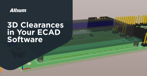
- 3D Contextual Clarity: Visualize PCB components and placement in full 3D within the mechanical environment. Avoid conflicts in mounting, clearance, and enclosure fit.
- Change Notifications and History: Stay informed of changes and who actioned certain elements of the design. MCAD codesign also maintains a log of design updates for traceability and reviews.
- Early Fit and Form Validations: Use 3D models to check alignment, clearance, and mechanical constraints before prototyping, significantly reducing iteration cycles.
- Easy Collaboration with ECAD Teams: Share design intent whether or not you understand electrical schematics. See only information relevant to your role, formatted for mechanical workflows.
MCAD codesign eliminates file-based miscommunication, affords engineers the ability to compress their design timelines, and aids mechanical engineers in contributing to designs with greater precision.
Whether you need to build reliable power electronics or advanced digital systems, Altium Develop unites every discipline into one collaborative force. Free from silos. Free from limits. It’s where engineers, designers, and innovators work as one to co-create without constraints. Experience Altium Develop today!

About Author
Related Resources
Related Technical Documentation
Table of Contents
- Departments Converge: EEs, MEs, and the Supply Chain
- Cross-Disciplinary Collaboration Points
- What MEs Need From EEs
- What EEs Need from MEs
- Why EE and ME Collaboration Breaks Down
- Flow of Data Among EEs and MEs
- Translating PCB and Mechanical Design Languages
- Version Drift Between Engineers
- Late Design Reviews
- Pressures on EEs and MEs
- Collaborate in Real Time with MCAD Codesign
- Key Features of MCAD Codesign Integration for Mechanical Engineers
Design to Release, Without the Friction
- Keep reviews tied to the right version
- Reduce handoff confusion and rework
- Spot sourcing and release risk earlier
- Work solo, share when needed
Get Started
Thank you, you are now subscribed to updates.
