


Flexible Circuits: Start with the Basics

At a Glance
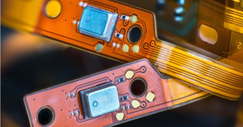
There are several advantages to using flexible materials. Size, weight, the ability to bend around corners and to flex during use to name just a few. Read this blog to learn more!


Have you been considering flexible circuits to solve a PCB design constraint? There are several advantages to using flexible materials. Size, weight, the ability to bend around corners and to flex during use to name just a few. If would like to learn more about these benefits, check out my previous blog post.
If you have read my past blogs, you will notice one common theme for those new to flexible circuit design, communicate with your fabricator before you begin and throughout the process. Flexible circuit fabricators are an excellent resource to learn about materials and how to design for flexibility and performance.
Sometimes it can be hard to reach out to ask questions before you begin. Let’s go through a high-level overview of the flexible circuit and rigid flex circuit design specifications and considerations to prepare for that initial conversation.
Basic Definition:
Flex and Rigid Flex Technology: A pattern of conductive traces bonded on a flexible substrate. There are several materials available, with polyimide being the most common. TIP: Flexible laminates typically use rolled annealed copper rather than electro-deposited copper for flexibility. If you have a dynamic flex application, pay close attention to this. As the name implies, a rigid flex construction incorporates rigid materials into the stack up and most common rigid materials are compatible with polyimide flex materials.
Flexible Materials:
- Adhesive based: using a layer of acrylic or epoxy to bond the copper to the flex core.
- Adhesiveless: thermoplastic polymide is bonded directly to the copper.
- Coverlay: A dielectric layer bonded to the outer layers, similar to soldermask in rigid PCB construction.
- Stiffeners: Non-reinforced polyimide or rigid materials used to support component areas or protect a specific area of the circuit board.
Flexible Circuit Specs and Types:
IPC-2223B Flexible Printed Board Design
IPC-6013 Qualification and Performance Spec
Type 1: Single sided construction
Type 2: Double sided construction
Type 3: Multi-layer construction
Type 4: Rigid Flex construction
Type 5: Rigid Flex without plated thru holes.
Tip: When designing a multilayer flexible circuit or rigid flex construction, adhesiveless materials are recommended.
- IPC 4101: Materials specification for rigid laminates
- IPC 4102: Materials specification for flexible base dielectrics
- IPC 4203: Materials specification for adhesive coated dielectric films for coverlay
Tip: When you have an idea of the number of layers and construction type you will be using for your flexible circuit design, work with your fabricator to understand the most commonly stocked and readily available materials to avoid inadvertently designing in added cost and lead time.
Project specific flexible circuit design considerations:
- Electrical performance: layer count, materials, impedance and shielding requirements
- Mechanical performance: profile tolerances, bendability and flexible requirements, access within enclosure
- Environmental: will materials withstand environmental and physical stresses
- Thermal: polyimide materials have excellent thermal conductivity, analyze and confirm materials will perform and include review of rigid materials if using a rigid flex construction
Flexible circuit specific design considerations:
Tip: These are the things that I highly suggest working with your fabricator on and drawing from their expertise for two reasons. First, every flexible circuit fabricator will have slightly different equipment and processing parameters and second, and most importantly, they have reviewed hundreds or thousands of designs and have seen the successes and corrected the failures when a flex circuit doesn’t perform as expected.
- Performance class: Does this need to be Class 1, 2 or 3?
- Copper flexibility: Critical to design, copper weight, materials, trace routing in bend areas
- Coverlay: typically, mechanically drilled, understanding “squeeze out” of acrylic adhesive, coverlay registration is not the same as soldermask registration on rigid printed circuit boards.
- Trace Routing: all corners, profile and traces should be rounded, no sharp edges, all pads should have teardrops/fillets and anchor pads.
- I-Beam effect: traces on adjacent layers should be staggered to avoid unnecessary stress on copper areas when bending and folding.
- Trace transition: Avoid vias or transition of trace direction in bend and fold areas.
- Stiffeners: should overlap coverlay end point to avoid stress and potential cracking or breaking. At stiffener interface, a bead of epoxy is recommended to alleviate stress.
- Bend radius is critical: IPC 2223 outlines bend radius rules flexible circuit type.
Some things that don’t change:
- Final surface finish: all common surface finishes are compatible with polymide materials.
- Testing: Electrical testing for continuity and impedance control testing is similar to rigid construction. Fabrication drawing and design package: overall package requirements are similar with consideration given to materials and performance specifications for flexible circuits and rigid flex circuits.
While this is a very high-level overview of things to consider when transitioning from rigid printed circuit board design to flex and rigid flex PCB’s and it provides a good starting point, the devil will be in the details, as they say. To repeat myself, just one more time, working with your fabricator to shorten the learning curve is an excellent place to start. You can also look forward to diving into these categories in more detail over the next few blog posts. In the meantime, please reach out with any flex related design questions!
About Author
Related Resources
Related Technical Documentation
Table of Contents
Design to Release, Without the Friction
- Keep reviews tied to the right version
- Reduce handoff confusion and rework
- Spot sourcing and release risk earlier
- Work solo, share when needed
Get Started
Thank you, you are now subscribed to updates.

