


Getting the Most From Your DC Electronic Load

At a Glance
A DC electronic load is needed for load testing your power supply, including transient testing.


One of the important tests used to qualify power systems is a load test, where power is delivered to a test load while the system is monitored. It is possible to use something as simple as a large power resistor, but higher loads require a piece of precision test equipment to evaluate. The standard piece of equipment we use in electronics is a DC electronic load, which is essentially a programmable load for testing DC power delivery from a circuit.
A DC load can be very simple, essentially consuming only DC power based on the load settings. Some DC loads have more advanced features or are programmable to simulate transients, power ramping, or pulsed power delivery. If you need to test a power system for commercial usage, then you should take advantage of certain features on your DC electronic load. Here is how these units work and some tests you can perform.
Features in a DC Electronic Load
All DC loads include a set of features that allow experimentation with different types of power regulators. These features include:
- Constant voltage control
- Constant current control
- Constant power control
- Constant resistance control
Each of these four operating modes is used to test different types of regulation methods in power systems. Based on the data provided in these different regulation modes, a DC electronic load instrument can be used to measure power conversion efficiency directly. These systems also provide a way to test other aspects of the system, such as thermal behavior and to investigate sources of EMI at high power.
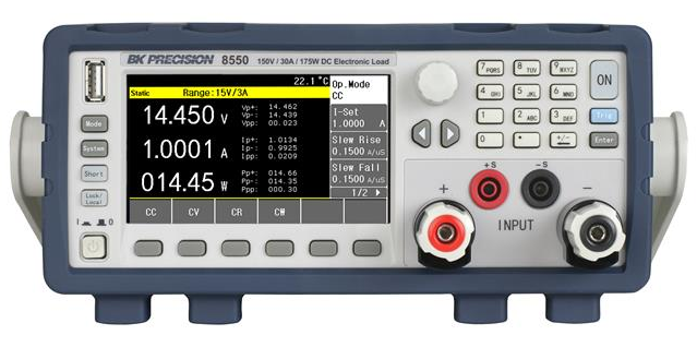
BK Precision 8550 DC electronic load
DC Load Testing Method
The first aspect of getting accurate data for your power system performance is to choose the right load testing method. The four DC load modes mentioned above are used for different types of power regulators; these are summarized below.
|
Constant power |
|
|
Constant voltage |
|
|
Constant current |
|
|
Constant resistance |
|
All of these assume the load is connected to a DC power. The load could be changed between DC values, and the instrument will register changes as long as the rate of change is slow enough.
Power regulators meant to deliver high power are switching regulators that use feedback to regulate to a specific output voltage. With a DC electronic load, the control loop at DC can also be examined, or noise can be injected and used to examine the regulation ability of the circuit. However, real digital systems are not running at DC, they are running at AC. DC electronic loads meant for testing these regulator circuits or VRMs need another feature that enables this kind of testing.
Transient Response
Some DC loads will have a transient feature or a step function feature that allows the AC response of a DC regulator to be measured. Essentially, the transient function will turn on power delivery to the internal load circuitry over a very short rise time, mimicking a step function on the input. The power regulator circuit very quickly goes from low power delivery to high power delivery, and the regulator circuitry and feedback loop needed to compensate for this step change in output power. The resulting response during this load test can be measured, normally in conjunction with another instrument (an oscilloscope).
What can you learn from a transient measurement with a DC load? There are a few important things that can be examined:
- Burst EMI during the load step
- Inrush on the regulator circuit’s input
- Output voltage droop on an upstream power supply
- Driving a regulator into instability or sustained oscillation
- Time to ramp up to full power output after the load step
All of the above will require an oscilloscope, or a spectrum analyzer in the case of burst EMI.
Transient Modes and Sweeps
Oftentimes, when attempting to simulate a high-power load on a regulator, we don't just want to look at single transient events. Regulators in a commercial system may need to sustain multiple transient events, some of which may arise randomly. The system then needs to be able to compensate for large single events, as well as repeated random events, sometimes varying in delay and magnitude.
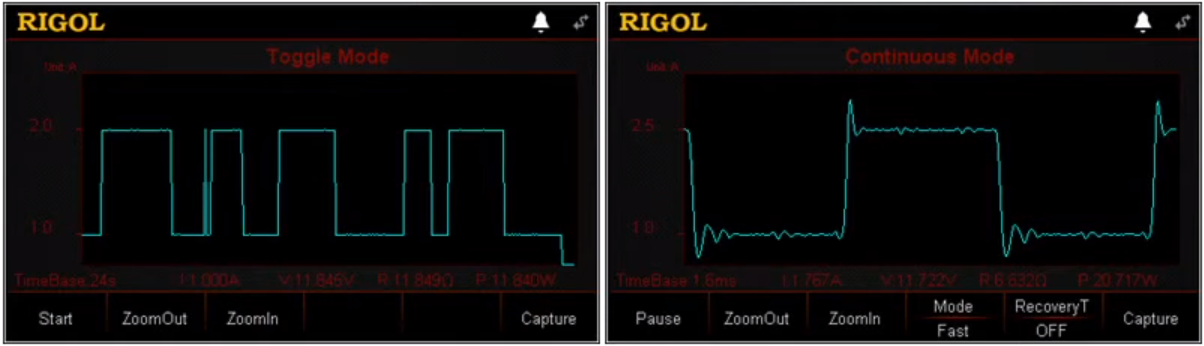
For example, the Rigol DL3000 series electronic loads allow continuous streams of pulses and ramping through a list of possible test values. This toggling allows simulation of periodic or random changes in the load and brings testing closer to what you might expect in a real system.
Transient mode configuration in a DC load. (Image from Rigol DL3000 configuration)
Rigol’s load shown above, as well as other loads, can even superimpose a ringing wave on the load steps. This would be needed to test control loop response in a power regulator or VRM.
What it does not tell you is the response of the regulator circuit and your circuit board’s PDN to changes in the load. For that, you would need a test board with probe access and a specialized probe that can handle power delivery over very broad bandwidths. This much more specialized time domain measurement involves multiple instruments and is something that I'll save for a future article.
Whether you need to build reliable power electronics or advanced digital systems, use the complete set of PCB design features and world-class CAD tools in Altium Designer®. To implement collaboration in today’s cross-disciplinary environment, innovative companies are using the Altium 365™ platform to easily share design data and put projects into manufacturing.
We have only scratched the surface of what’s possible with Altium Designer on Altium 365. Start your free trial of Altium Designer + Altium 365 today.

About Author
Related Resources
Table of Contents
Design to Release, Without the Friction
- Keep reviews tied to the right version
- Reduce handoff confusion and rework
- Spot sourcing and release risk earlier
- Work solo, share when needed
Get Started
Thank you, you are now subscribed to updates.

