


How to Get the Most Out of Your Analog Front-End

At a Glance
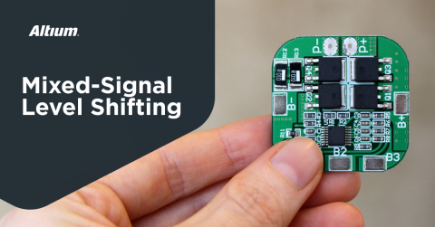
Implement dedicated sensor front ends with GreenPAK. Build on-chip signal conditioning, threshold detection, timing qualification, and output encoding using the free Go Configure Software Hub.


An analog front end should do more than pass a sensor signal into an ADC. In many embedded systems, the useful output is a clean decision, a qualified event, a fault flag, a valid-window indication, or a compact digital state that the controller can act on immediately. When the front end is designed around the information the system needs, it can reduce firmware overhead and make the signal path more deterministic.
GreenPAK devices are useful in this role because they combine analog resources and configurable digital logic in a small mixed-signal IC. Comparators, references, ADC resources, counters, LUTs, latches, and output drivers can be used together to condition the signal, reject invalid behavior, classify operating states, and generate system-ready outputs. This article looks at how to get more from an analog front end by treating it as a complete signal interpretation block rather than a simple analog input stage.
Start With the Signal Requirement
A useful analog front end starts with the signal requirement and the decision the system has to make from that signal. The expected amplitude range, source impedance, noise level, bandwidth, transient behavior, and response time all determine whether the front end should use gain, attenuation, filtering, threshold detection, ADC sampling, or some combination of these functions. A slow thermistor input and a fast current-sense input can both produce low-voltage analog signals, but they create very different requirements for filtering, delay, threshold accuracy, and fault response.
The required output format should also be defined early:
- Does the signal only need to produce a fault output, power-good indication, valid-window result, or interrupt?
- Does the system need multiple operating regions, such as low, normal, warning, and shutdown?
- Should the front end classify the analog input before the controller reads it?
- Does the signal require trend data, calibration, or reporting?
- Is an ADC path appropriate, or can the required decision be handled with thresholds and logic?
For signals that require measured values, the front end still has to control signal range, noise, and input settling before conversion. For simpler monitoring and protection functions, the output requirement may point to a smaller threshold-based implementation.
This requirement-driven approach usually produces a cleaner circuit than routing every analog signal directly into an MCU’s ADC pins and handling all decisions in firmware. A comparator, reference, delay block, and latch may be enough for a qualified fault signal. Multiple thresholds and simple logic can convert a sensor input into a compact state code. An ADC can be reserved for signals where measured value matters. Defining the signal requirement first keeps the front end tied to the system behavior it is supposed to support.
Use the Front-End to Reduce Firmware Effort
Analog interpretation in firmware is reasonable when the signal changes slowly and the controller has unused ADC bandwidth. It becomes a poor allocation of system resources when the MCU has to continuously poll rails, current monitors, sensor thresholds, and fault indicators that can be resolved before they reach the processor. Every sampled signal brings acquisition time, filtering logic, range checks, state handling, and validation effort into firmware. Those routines also inherit scheduler latency, interrupt priority conflicts, ADC mux timing, and startup-state edge cases.
A better front-end partition moves repetitive analog decisions into hardware and sends the controller a qualified result. This is especially useful when the system response is already known from the analog condition. Overcurrent, undervoltage, overtemperature, sensor-valid, and power-good signals rarely need continuous firmware interpretation if the threshold, timing, and reset behavior are already defined.
|
Front-End Function |
Equivalent Firmware Function |
System-Level Benefit |
|
Threshold detection |
Repeated ADC sampling and limit checks |
Faster fault or status response |
|
Window validation |
Upper/lower range comparisons |
Cleaner power-good or sensor-valid indication |
|
Delay or debounce |
Software filtering and event qualification |
Fewer false interrupts from noise or startup transients |
|
Blanking interval |
Special-case firmware handling during switching or startup |
Reduced nuisance faults during known transient periods |
|
Fault latch |
Persistent fault-state management |
Easier event logging and controlled reset behavior |
The functions that belong in the front end usually have simple analog criteria and a defined system response. A current-sense voltage can assert an overload signal directly. A window detector can report whether a rail, sensor output, or bias node is inside its allowed operating range. Delay, debounce, blanking, and pulse stretching can prevent startup transients, switching spikes, and noisy threshold crossings from becoming firmware events. A latch can preserve a fault condition until the controller records it and performs a controlled reset sequence.

This partition also makes the product easier to validate. Firmware should configure limits, log events, communicate status, and manage product behavior. The front end should handle continuous analog supervision and deliver clean state information. In power sequencing, battery protection, motor drives, load switching, and sensor supervision, this keeps the response path deterministic and reduces the amount of software that has to be proven correct under transient operating conditions.
Simplify Your Analog Front-End With GreenPAK
GreenPAK is a family of configurable mixed-signal ICs from Renesas that combines analog blocks (comparators, op-amps, voltage references, ADCs) with digital logic elements (LUTs, counters, delay blocks, latches) in a compact, low-power package. Its non-volatile memory allows it to power up with pre-defined behavior, eliminating the need for a boot sequence or external processor. This integration makes GreenPAK well suited to dedicated sensor front ends, enabling on-chip signal conditioning, threshold detection, timing qualification, and output encoding.
Designers build and simulate complete analog front-end configurations using the Go Configure Software Hub from Renesas. This free tool offers a schematic-style design environment for placing, connecting, and parameterizing internal blocks, along with simulation capabilities to verify circuit behavior before hardware programming. A designer can prototype a sensor interface, validate behavior in simulation, and program a physical device in one session, compressing the iteration cycle from days of board rework to minutes of configuration adjustment and resimulation.
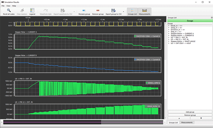
The Go Configure software suite from Renesas includes simulation of your GreenPAK design.
To learn more, take a look at the GreenPAK components and reference examples.
Whether you need to build reliable power electronics or advanced digital systems, use the complete set of PCB design features and world-class CAD tools offered by Altium to implement your GreenPAK solutions. Altium provides the world’s premier electronic product development platform, complete with the industry’s best PCB design tools and cross-disciplinary collaboration features for advanced design teams. Contact an expert at Altium today!
Related Resources
Related Technical Documentation
Table of Contents
Design to Release, Without the Friction
- Keep reviews tied to the right version
- Reduce handoff confusion and rework
- Spot sourcing and release risk earlier
- Work solo, share when needed
Get Started
Thank you, you are now subscribed to updates.

