


How to Catch Enclosure and Connector Misalignment Before the First Prototype

At a Glance
Catch ECAD-MCAD misalignments early. Learn how to prevent enclosure and connector issues before prototyping slows your timeline or inflates costs.


As electronics continue to shrink, PCB designers face unprecedented demands for precision. However, gaps between ECAD and MCAD processes still lead to costly misalignment issues.
Precision is required at every stage of engineering and manufacturing, yet certain elements remain out of sync. Misalignments in enclosures and connectors often stem from a lack of cohesion between electronic and mechanical design. These issues frequently surface during prototyping, and while they may be caught before production, resolving them can still be both costly and time-consuming.
Recognizing the problem naturally points to the solution: electronic and mechanical engineers must work with consistency and clarity, integrating their design platforms to ensure data transparency. Before exploring this integration further, let’s take a closer look at the specific causes of and remedies for component misalignment.
Key Takeaways
- Design misalignment is a major cost driver. Gaps between ECAD and MCAD workflows often cause enclosure and connector misalignment that surfaces late in prototyping, leading to rework, delays, and supply-chain disruption.
- Root causes are process, not precision. Manual file exchanges, siloed teams, assumed connector geometry, and missing shared design rules create version drift and lost design intent across disciplines.
- Early, shared mechanical context is critical. Accurate 3D models, component height/orientation data, tolerance awareness, and cross-discipline reviews are essential to prevent fit and form issues in dense designs.
- MCAD co-design reduces risk and cycle time. Real-time, bidirectional ECAD-MCAD collaboration provides a single source of truth, cuts iteration cycles, and enables faster, more reliable product development.
Common Causes of Design Misalignment
Enclosure and connector misalignment remains a persistent (and costly) challenge in hardware development.
The issues often go unnoticed until the first prototype is assembled. While this might seem a better case than in the first rounds of manufacturing, it can still cost engineers design time as they refer back to their initial layout.
At this stage, the costs are felt throughout the supply chain as additional engineering causes delays or reorders. But why does this happen?
This is partly a result of the insights available to procurement teams. Generally speaking, sourcing efforts are based on the contents of Gerber files that typically exclude crucial mechanical factors, such as:
- Exact 3D positioning of connectors, buttons, and other mechanical components.
- Component height and orientation.
- Enclosure or housing specifications.
- Mounting hardwares, fixings, or keep-out zones for assembly.
- Tolerance information and other discrepancies within the bill of materials (reducing significantly in newer, more compact designs).
- Assembly notes and torque specifications.
This brings the focus to collaboration between electronic and mechanical designers. Poor collaboration in these design departments is a result of either disconnected workflows, outdated file exchange systems, assumptions on connector positioning, and a lack of shared data and reviews.
Disconnected Workflows Between ECAD and MCAD Teams
Electronic and mechanical teams are often siloed, with different tools, data, and timelines. The disjointed process leads to a fragile handoff, typically informal information sharing that invites human error into the assembly equation.
Manual File Exchanges and Version Drift
When the electronic computer-aided design (ECAD) and mechanical computer-aided design (MCAD) teams lack a shared, consistent, and updated design environment, their efforts are seldom aligned, which is reflected in the final prototype. Even a small delay in communication can result in a mechanical failing that does not match the electronic requirements. This is a generic cause of connector misplacement.
Assuming Connector Geometry and Mounting
Connectors are not just schematic symbols, but 3D components with height, orientation, and precise mounting requirements. Misunderstanding the placement of these can lead to a significant error that ripples through the supply chain. Identifying the source of misalignment early prevents deeper delays down the line.
With insight into the design, sourcing procurement teams are capable of sourcing in the development stage and desperately need to understand whether the issue is a result of poor fit or incorrect placement.
Lack of Shared Design Rules and References
If ECAD and MCAD teams are not fully clued up on design rules, coordinate origins, or how components are dimensioned, it is easy to allow inconsistencies to sneak in. While a connector may seem correctly placed in the electronics blueprint, a fault may occur in terms of mechanical placement, which can result in fitment issues or complete mechanical failure.
Infrequent and Unaccounted Reviews
Design reviews that take place in silos remain a consistent source of fit and form faults for some businesses. Without a collaborative view of the entire electromechanical structure, critical alignment issues can go unnoticed until physical parts are assembled.
Proactive Alignment Strategies for PCB Designers
Avoiding misalignment is not just about catching mistakes in the design process, but rather, aligning the design teams to ensure that such problems occur as infrequently as possible.
As PCBs are designed for density, and connector-enclosure position required to meet tighter specs, even a small mechanical oversight ripples down the line, causing costly reworks or procurement delays.
A proactive approach consists of improved collaboration between electronics and their mechanical counterparts. As they strive for precision, some of the following strategies could minimize flaws in their processes that later materialize as major production hindrances.
- Use accurate mechanical drawings and 3D models during PCB and enclosure design.
- Perform 3D checks in ECAD tools like Altium Develop PCB design environment.
- Add alignment features like mounting holes and positioning pegs to guide certain placements in the electronic side (not always suitable for components with less tolerance).
- Print or prototype enclosures and PCBs using 3D printing or CNC to validate fit.
- Encourage a better workflow between electronic and mechanical engineering times by integrating their designs.
MCAD Co-Design: Seamless ECAD-MCAD Collaboration
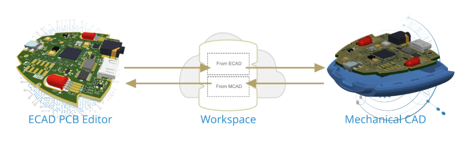
MCAD co-design enables real-time, bidirectional collaboration between ECAD and MCAD environments, connecting Altium design to industry-preferred tools like SolidWorks, PTC Creo, Autodesk Inventor, and Fusion 360. Instead of relying on manual file transfers between ECAD and MCAD, or outdated models, teams can instantly share design changes with full mechanical context, including 3D geometry and placement data.
Integrating such a solution directly into engineers’ favored tools helps maintain alignment across both disciplines, reducing the risk of miscommunication and rework. For teams working on increasingly complex or compact designs, access to this level of precision and collaboration can significantly reduce iteration cycles and speed up their development.
The Value of MCAD Co-Design for Teams and Stakeholders
For mechanical engineers, MCAD co-design eliminates the guesswork related to connect and enclosure alignment. Instead of working from static file exports or outdated models, they gain visibility of detailed board designs in real time within their native CAD environment.
Electronic designers experience fewer interruptions and faster iteration cycles. No more waiting for feedback or manually regenerating files to communicate intent, just a single source of truth shared across disciplines.
For all other stakeholders, manufacturers and all other downstream businesses, there is inherent value in fewer prototype iterations, shorter development cycles, reduced costs, and faster time to market. MCAD co-design aligns components, teams, objectives, and outcomes.
Conclusion
The industry is driven by the need for speed to market, coupled with increasing complexity and precision in both ECAD and MCAD designs, making efficiency the core of every intricate product. Yet, the balance between the two often leaves room for component misalignment, and the fast pace required can ultimately compromise the integrity of finished goods.
Capabilities like MCAD co-design empower teams to detect issues early, reduce costly reworks, and improve collaboration among teams in every stage of development. As devices become more compact and timelines tighten, bridging the gap between mechanics and electrical is a clear next step for more reliable innovation. When ECAD and MCAD align, teams move faster, avoid waste, and deliver better products on time and on spec.
Whether you need to build reliable power electronics or advanced digital systems, Altium Develop unites every discipline into one collaborative force. Free from silos. Free from limits. It’s where engineers, designers, and innovators work as one to co-create without constraints. Experience Altium Develop today!
Frequently Asked Questions
What causes enclosure and connector misalignment in PCB designs?
Misalignment most often comes from disconnected ECAD–MCAD workflows, manual file exchanges, assumptions about connector geometry, and missing mechanical context such as component height, orientation, tolerances, and enclosure constraints. These gaps usually surface during prototyping, when fixing them is already costly.
Why aren’t Gerber files enough to prevent mechanical fit issues?
Gerber files focus on electrical fabrication data and typically exclude critical mechanical details like 3D placement, connector height, enclosure geometry, mounting hardware, and assembly constraints. Without this information, mechanical and procurement teams are forced to make assumptions that can lead to misalignment.
How can PCB designers catch alignment problems earlier in the design process?
Early alignment improves when teams use accurate 3D component models, run 3D clearance checks in ECAD tools, validate designs with rapid prototyping (3D printing or CNC), and conduct shared ECAD–MCAD design reviews instead of siloed checks.
How does MCAD co-design reduce misalignment and rework?
MCAD co-design provides real-time, bidirectional synchronization between ECAD and MCAD tools, giving both teams a shared, up-to-date view of the design with full mechanical context. This eliminates version drift, reduces guesswork around connector and enclosure fit, and significantly cuts prototype iterations, delays, and costs.

About Author
Related Resources
Related Technical Documentation
Table of Contents
- Key Takeaways
- Common Causes of Design Misalignment
- Disconnected Workflows Between ECAD and MCAD Teams
- Manual File Exchanges and Version Drift
- Assuming Connector Geometry and Mounting
- Lack of Shared Design Rules and References
- Infrequent and Unaccounted Reviews
- Proactive Alignment Strategies for PCB Designers
- MCAD Co-Design: Seamless ECAD-MCAD Collaboration
- The Value of MCAD Co-Design for Teams and Stakeholders
- Conclusion
- Frequently Asked Questions
- What causes enclosure and connector misalignment in PCB designs?
- Why aren’t Gerber files enough to prevent mechanical fit issues?
- How can PCB designers catch alignment problems earlier in the design process?
- How does MCAD co-design reduce misalignment and rework?
Design to Release, Without the Friction
- Keep reviews tied to the right version
- Reduce handoff confusion and rework
- Spot sourcing and release risk earlier
- Work solo, share when needed
Get Started
Thank you, you are now subscribed to updates.
