How to Implement Supervised Inputs in Your PCB Circuit Design
Have you ever worked late on a design project and forgot to eat? I was literally starving when I finished off one of my regular design projects. I decided to go for a quick meal at a local eatery. I placed my order and hoped the service would be fast. However, after 45 minutes and no food, I was told that the kitchen has missed my order.
I learned my lesson that you can’t expect that your order is being followed just because you placed it. The same happens with dealing with inputs in an embedded system. A microcontroller that reads as ON (0V) from a door sensor input does not necessarily mean that the door is open. In some cases, it could simply mean that the wire connection is broken. There are ways to mitigate these false positives and negatives in your system, the most straightforward way is to use supervised inputs in PCB design and layout.
What Are Supervised Inputs
Supervised inputs are inputs that are capable of reporting more than two states to the monitoring device. Non-supervised inputs, which are more, can only measure two states: ON and OFF. In terms of electronics, these ON and OFF states are represented by 0V and the voltage level that the microcontroller (MCU) operates at. For the sake of discussion, let’s say that it is 3.3V.
How A Non-Supervised Input Is Commonly Wired.
Non-supervised inputs are limited because the system is unable to detect process cable faults or when the system is being intentionally tampered with. A good example of this is when a magnetic switch is used to detect whether a door is closed or opened. If the cable connecting the magnetic switch to the electronics system brakes, the MCU will detect it as a door open event. And the MCU will falsely detect a door close event when the wire is intentionally short-circuited.
Having only two supervised states result in safety and security risks. In those scenarios, these failures can have costly repercussions. A supervised input, on the other hand, allows the system to have up to 4 possible states in the input. These are typically ON, OFF, FAULT-SHORT, and FAULT-OPEN. The additional two input states allow you to detect if the connecting cable is broken or short-circuited.
How To Implement Supervised Inputs In Your PCB Design
Incorporating supervised inputs might seem simple, but to be functional they require a combined effort among the Printed Circuit Board, firmware programmer, and the system installer. Instead of digital inputs, PCB designers need to connect the signals to analog inputs as the system now requires 4 states of logic instead of 2.
The whole concept of supervised inputs revolves around the principle of the voltage divider. The system uses 3 resistors to create various voltage levels with respect to the situation. For example, an opened switch results in 3.3V for a non-supervised digital input, but a supervised input with the above configuration would read 2.2V. The responsibility of the firmware programmer is to take the analog value and determine the state of the input by comparing it to threshold values between the different states.
Last but not least, the system installer must install two resistors close to the switch. One resistor is connected in parallel and another is connected in series to the switch. The value of the resistor needs to be exactly as specified by the Circuit Board designer to ensure that the firmware behaves accurately.
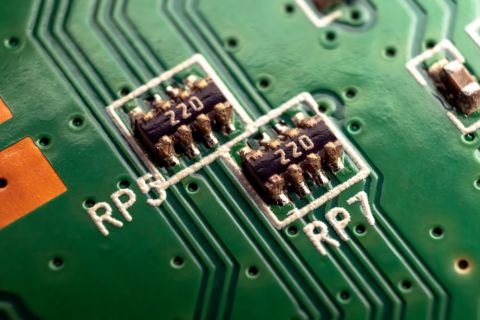
A close-up of a PCB routing board
Ensuring Reliable Readings From Your Supervised Inputs
The key in providing reliable analog readings in supervised inputs in PCB design is to incorporate good analog design practices. You’ll want to ensure that the analog signals are not subjected to cross-talk or other electrical interference that can produce fluctuating values. While digital inputs have a reasonably large threshold between logics, a supervised input has a smaller tolerance in terms of logic state threshold. This is especially the case when you’re operating at a lower voltage.
There is no reasons not to implement supervisory inputs in figh frequency designs whose applications are susceptible to tampering and wiring faults. After all, it is pretty straightforward to design supervisory inputs using an additional two resistors and an analog channel instead of digital one. Of course, you’ll need to ensure your analog connections are routed with best practices in mind.
I make it a point of maintaining clearance between high-speed signals and analog supervisory inputs. When you need to access an easy-to-use PCB layout tool that includes everything needed to build high-quality manufacturable circuit boards, look no further than CircuitMaker. In addition to easy-to-use PCB design software, all CircuitMaker users have access to a personal workspace on the Altium 365 platform. You can upload and store your design data in the cloud, and you can easily view your projects via your web browser in a secure platform.
Start using CircuitMaker today and stay tuned for the new CircuitMaker Pro from Altium.

