


How to Design for Test in Embedded Systems

Whether you're designing a high-speed PCB, or a complex embedded system, it will need some level of testing. For the advanced high-speed and RF systems, that usually means simulations compared to VNA or scope measurements. For embedded software and firmware, the testing steps can be quite different. In fact, there are some things you can do in your prototype design to help you speed up the testing process and eliminate the need to probe around with a multimeter.
In this article, I'll show you some simple tricks that can make testing and debugging a prototype much easier. This means taking a design for test approach and applying it to both software and hardware. Here's a hint: the best path for embedded systems testing involves more than just placing test pads or test points.
Design For Test in Embedded Hardware
We have a lot of buzzwords in the PCB industry, and “design for test” is usually grouped in with the broader DfX bundle. A lot of designers will approach design for tests for a board that runs embedded code in the same way they would approach testing for any other board.
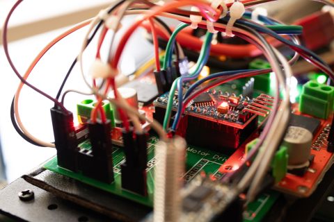
This usually means designers will place a lot of test points on important signals, but maybe not much else. A lot of embedded prototypes will start to look like an Arduino dev board, where everything you can think of on the main processor is routed out to pin headers and test points.

I have nothing against pin headers on an embedded systems board, or on any other board for that matter. But, it's difficult to monitor every signal and pin while also trying to test and debug software or firmware running on the board. In some cases you have to actually write an application just to test your application. Sometimes, if you see an error in your design’s functions, it might not always be obvious whether the root cause is in your code or in your PCBA.
On the hardware side, focus on taking this simplified approach to design for test:
- Not everything needs a pin header. Take a signal out to a header if you actually plan to connect it to something or if you’ll actually measure it.
- Place connectors you can actually use. This way you could wire up to a data acquisition card, logic analyzer, oscilloscope, etc.
- Have the software do the testing. Don't forget that your embedded application can read signals from peripherals, which lets you build test cases into your code.
- You can look at data on screen, you just need a connection to your PC, such as through a serial port, data acquisition card, or proprietary software.
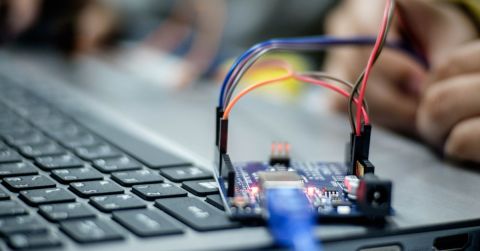
Some of these concepts have been discussed a lot by Ari Mahpour in his discussions on testing and continuous integration. Take a look at this article to learn more about this approach. If you want to send data back to your computer, the simplest method is to add a USB-to-serial interface to your prototype. Take a look at this project from Zach Peterson and grab the link design files.

Test Cases in Embedded Software
Next, if you're running an embedded application on your system, then you can include error handling or test cases in the code to help speed up testing. Adding the connections to interfaces with headers, test pads, and a basic serial interface are all important steps that help you monitor your embedded board in real time. The goal is to see how the software application behaves right alongside the hardware.
So how can you monitor the progress of your application and hardware simultaneously? Take a cue from software developers: add in error handling and messages to display the status of each function in your application. This can be as simple as displaying messages stating whether important functions passed or failed in the application. It takes some extra time to write out all those error checks, having an on-screen message indicating what your system is doing during application execution can eliminate a ton of debugging.
Here’s an example that shows how this would be implemented in C/C++ using a simple function (called myFunction()) and a hypothetical GPIO library. Let's assume you're working with a platform that provides a simple GPIO library with functions like gpio_init(), gpio_read(), etc.:
|
#include <iostream> |
If your application is monitoring signals directly, your application can print those results at each step in its core functions. Printing these on screen along with your key indicator signals will tell you exactly what's happening as your application progresses, and you won’t need to manually measure every signal across your board with an external unit. Sure, it requires routing a few extra traces to GPIOs when designing the board, but you might find that an apparent logic error was really just a simple connection error in your PCB.
Don't forget, you can still take any other signals that need to go to a probe over to a header. This way, those signals can still be measured with a scope, or a data acquisition card. Meanwhile, the serial port will do a lot of the work of helping you interact with your application logic.
No matter what you want to design, you can implement innovative design for test practices using the complete set of PCB design features in Altium Designer®. To implement collaboration in today’s cross-disciplinary environment, innovative companies are using the Altium 365™ platform to easily share design data and put projects into manufacturing.
We have only scratched the surface of what’s possible with Altium Designer on Altium 365. Start your free trial of Altium Designer + Altium 365 today.
About Author
Related Resources
Related Technical Documentation
Table of Contents
Altium is transforming the electronics industry so thoroughly that our web pages need a minute to catch up. For a short time, some information on this page may be outdated.
We appreciate your patience. It will be worth the wait!
Learn More
Thank you, you are now subscribed to updates.