Managing a 7-Segment LED Display Array With Minimal Pins
In my early 20s, I prided myself on my ability to multitask. On a moment’s notice, I could switch between multiple projects and wear the hats of the procurement officer, engineer, technician, marketing manager, and support specialist while simultaneously running my electronics startup. I thought it was a blessing to be able to multitask.
A decade later, I realize that multitasking results in lower work quality while killing my brain in the process. No wonder I’m forgetting everything as I get older! Multitasking, clearly, was an unsustainable habit when it came to my workflow. In electronics design, however, switching between tasks, or rather pins, makes it possible to control 7-segment LED arrays with minimal pins.
How a 7-Segment LED Display Works
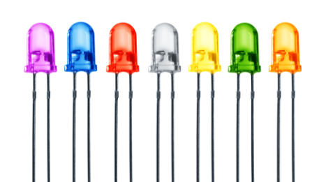
A 7 segment LED display is a numeric indicator consisting of seven LEDs arranged in a rectangular shape. The basis of operating a 7-segment display is the same as driving regular LEDs, which require a forward voltage to turn on as well as limiting resistors for the current flowing through each LED.
You’ll find that a 7-segment LED display contains 8 pins. Seven of the pins control one end of the individual LED while one common pin controls the cathode or anode of the LED, depending on the type of segment display. The current needed to turn on the LEDs also varies with the size of the 7-segment displays.
In electronics, 7-segment LED displays are common in counters and timers, which show numbers as well as alphabets by lighting up the appropriate LED. They are easily available and easier to implement than arranging multiple single LEDs to achieve the same purpose.
7-segment LED display come in various shapes and sizes. Smaller sizes are typically driven directly by a microcontroller or a logic chip’s output pins. LED displays that are larger and consume more current usually utilize transistors to sink or source the current.
Controlling 7-Segment LED Display Arrays With Minimal Pins
Controlling a single 7-segment LED display is easy, as it involves only seven pins and permanently connecting the display common to either ground or positive supply. A single segment, however, has limited functionality in actual applications. For instance, timer or counter applications often require connecting two or more 7-segment LED displays. As an example, a vehicle counter in a parking space requires at least 4 segments for practical usage.
Driving arrays of 7-segment LED displays can involve connecting each control pin to a dedicated output. However, this results in an extremely high level of pin usage on either a microcontroller or a latch integrated circuit (IC). As a result, this configuration requires 28 pins for 4-segment displays.
A better way to lower the pin count is to connect all seven segment control pins to the same set of outputs and connect the common pins of each individual segment to a specific output. This connection mode allows only a single 7-segment display to be turned on at any given time.
How to Use Firmware to Drive 7-Segment LED Display Arrays
So, you’ve managed to reduce the pin count for 4-segment displays to 11 pins instead of 28. Well done! Now, how will you ensure that all segments are showing the right numbers together? Technically, it’s an impossible task but you can make it happen, thanks to the limitations of the human eye and some ingenious firmware programming.
The human eye can only detect changes in motions or flickers up to 60Hz, although some experts may argue differently. A microcontroller is so powerful that it can switch on each of the 7-segment LED displays sequentially and in higher frequency. The end result is the illusion of all four displays being turned on together and displaying the right numbers.
The key here is to store the desired alphanumeric value on a memory array and turn on the right output pins at a specific interval. This method can be applied when you have a larger number of 7-segment displays to control. The only factor you need to be aware of is the microcontroller’s ability to achieve a faster refresh rate and therefore cause a potential electrical interference with high-speed switching.
PCB Design to Reduce Pin Counts of 7-Segment LED Arrays
To control 7-segment LED arrays while minimizing the number of pins, it is necessary to diligently monitor LED arrangement and pin connection. Adhering to the basic rules of PCB design is also critical, especially when you have analog signals that are sensitive to noise.
When you need to access an easy-to-use PCB layout tool that includes everything needed to build high-quality manufacturable circuit boards, look no further than CircuitMaker. In addition to easy-to-use PCB design software, all CircuitMaker users have access to a personal workspace on the Altium 365 platform. You can upload and store your design data in the cloud, and you can easily view your projects via your web browser in a secure platform.
Start using CircuitMaker today and stay tuned for the new CircuitMaker Pro from Altium.




 Back
Back