PCB Relay Selection, Design, and Layout are Easy in Altium Designer

Circuit protection is vital for user safety and for protecting a board from electrical damage. Whether you’re working with a small, moderate power PCB or a large, high voltage electromechanical system, power surges or faults can destroy components and create hazards for users. The best way to ensure your next device remains safe from high voltage ESD or large current surges is to use a simple PCB relay.
Compared to large relays that need to be mounted on a metal enclosure, a PCB relay can mount directly on your circuit board as a through-hole component. This gives you a simple way to protect your board and its components from electrical hazards. When you want to place and use a PCB relay in your next system, Allium Designer makes the selection and placement process easy. Keep your high voltage/high current designs on track and get through the sourcing process quickly with Altium Designer.
ALTIUM DESIGNER®
The only application with industry-standard design tools for PCB relay selection, layout, and routing in high voltage/high current circuit board designs.
Anytime you’re working with a high voltage or high current system, safety should be at top of mind. The dangers associated with high power systems are too great to leave component reliability to chance. However, there are many ways designers can protect themselves and their equipment from high voltage/high current discharge during operation.
One of the standard pieces of equipment used in any high voltage system is a relay. These switches come in a variety of sizes, including as a PCB relay that can mount to a circuit board. These components give high voltage systems the protection they need to remain reliable and to withstand power surges during operation.
What is a PCB Relay?
A PCB relay is a smaller relay that can mount directly to a PCB. These relays tend to have high voltage ratings and may mount to a board as through-hole components due to their size and weight. A relay is used whenever there is a need to control a high voltage circuit with a second low power circuit. The additional benefit of a relay is galvanic isolation, which is not available with transistor-based switching.
PCB relays function just like any other relay, but they tend to be more compact and have lower voltage ratings. These components also come in any of the standard constructions you would find in larger relays. These include:
- High-voltage: These are designed to work with very high voltage and current.
- Overcurrent: This type of relay opens to stop high currents from flowing in the wrong direction around a circuit.
- Semiconductor: These solid-state relays switch electronically.
- Time-delay: These relays trigger for a limited period of time.
- Thermal: These relays will trip once the temperature exceeds a certain threshold.
- Differential protection: This type of PCB relay can trigger when two different parts of a circuit have different voltages or currents.
- Frequency protection: These solid-state relays trip when the frequency of an AC current is too high or too.
Each type of relay has uses in particular applications, but they are normally found in high voltage PCBs and high current circuits.
High Voltage Protection in Your PCB
Overall, PCB relays can be used as critical protection devices that will trip when they receive a high current in the armature coil. In the event there is a high current in a PCB relay, the relay can trip and leave an open circuit, which then breaks current flow in the device. However, relays are not the only way to apply protection against ESD in high power circuits.
If your next board will run at high voltage and requires some protection, you may need multiple protection devices like TVS diodes, fuses, and gas discharge tubes to withstand power surges. In addition to safety components, high voltage designs need to be laid out according to specific safety rules to prevent discharge within the system and to end users. With the right PCB layout software, it’s easy to follow these design rules and place circuit protection devices in your PCB.
- Rules-driven design software will help you follow industry standards on high voltage circuit boards so that your board will be safe during operation.
- If your PCB will run at a high current, you need to follow some best practices for designing traces to prevent excessive temperature rise.
Learn more about design rules and industry standards for high current PCBs.
- Relay circuits on a PCB may need some additional components to provide sufficient protection against overvoltage/overcurrent.
Learn more about using a flyback diode with your PCB relay circuits.

Dense high voltage designs need overvoltage and overcurrent protection with PCB relays and other components.
Finding and Sourcing PCB Relays
With so many different types of PCB relays on the market, how can designers find the relay they need to circuit protection? You shouldn’t have to browse distributor ot manufacturer websites. Instead, you need supply chain tools inside your PCB design software to help you source the relays you need and add them to your design.
Altium Designer gives you the supply chain visibility you need to find to find the relays you need for your high-power circuit board. The supply chain features in Altium Designer will do more than just show you component lists. You can search through the supply chain with filtration features, search by component type/description, and look at distributor stocks as you prepare your orders. You can find the PCB relays your high voltage circuits need for protection with the supply chain features in Altium Designer.
Altium Designer Helps You Prepare Power Systems for Production
Once you’ve placed the right PCB relays and finished your circuit board layout, Altium Designer’s manufacturing features help you quickly prepare for full-scale production. Whether you’re designing a high power board or an advanced digital system, you can prepare any new design for production with Altium Designer’s sourcing and manufacturing features.
- The complete set of design features in Altium Designer give you access to the electronics supply chain, which helps you find PCB relays for your new circuit board.
Learn more about designing high voltage PCBs to cost with supply chain visibility.
- Once you’ve found the components and the relays you need in your circuit board, you can finalize your production order and budget with the ActiveBOM utility in Altium Designer.
Learn more about using ActiveBOM to help you source components.
- The Manufacturer Part Search panel in Altium Designer helps you quickly find PCB relays for your next electromechanical system. You can instantly download relays to your component libraries and start placing them in your PCB layout.
Learn more about the Manufacturer Part Search panel in Altium Designer.
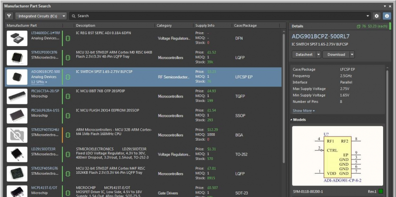
The Manufacturer Part Search panel in Altium Designer gives you a great estimate of prices and helps you find PCB footprints for your libraries.
Everything You Need for PCB Relays is in Altium Designer
To keep a new product safe, designer teams working on high voltage systems need a complete set of layout, evaluation, simulation, and sourcing features. PCB relays can be easily sourced and added to a new board with Altium Designer’s supply chain tools and instantly put into your circuit board layout. You won’t have to switch between applications to design high-quality circuit boards, source components, and prepare for fabrication. Everything you need is unified in a single application.
Altium Designer’s integration between design, manufacturing, simulation, and evaluation comes from its underlying rules-driven design engine. All of the design features in Altium Designer are built on the same application engine that enforces a single set of design rules throughout the application. Everything happens in a single program and allows you to spot errors in your board as soon as they happen, rather than waiting until a design is completed.
Rules-Driven Design for High Power Boards in Altium Designer
Thanks to the complete set of rules-driven PCB design tools, designers can ensure their circuit boards with PCB relays will be designed to industry safety and reliability standards. IPC, IEC/UL, and other standards can be encoded as design rules, and these rules will interface with every PCB layout tool in Altium Designer. The DRC engine runs as you create your board and flags errors in real-time, which keeps your design safe and your productivity high.
- The complete set of circuit board layout features in Altium Designer are ideal for building your electromechanical systems, high power systems, and high-speed digital systems for any application.
Learn more about working in Altium Designer’s unified environment.
- Simulation tools are vital for high voltage designs, including in designs that need protection from overvoltage/overcurrent. The PDN Analyzer extension for Altium Designer gives you simulation tools for evaluating high voltage designs.
- When you use the Altium 365 platform, you’ll have access to a complete solution for component data management and sourcing. All data is instantly accessible within Altium Designer or in a web browser.

Altium Designer’s complete set of CAD features gives PCB relay designers a realistic view of their boards in 2D and 3D.
The next time you need to source, place, and route PCB relays in your circuit board, use the industry-standard PCB design features in Altium Designer. You’ll have everything you need to take control of your designs and prepare them for full-scale production. Once you’ve finished your design, you can share your data with collaborators on the cloud with the Altium 365 platform. No other design application provides this type of connected, collaborative experience.
Altium Designer on Altium 365 delivers unprecedented integration to the electronics industry until now relegated to the world of software development, allowing designers to work from home and reach unprecedented levels of efficiency.
We have only scratched the surface of what is possible to do with Altium Designer on Altium 365. You can check the product page for a more in-depth feature description or one of the On-Demand Webinars.


