Rigid-Flex PCBs: Advantages and Challenges

Innovation is driving the demand for smaller, smarter and more versatile devices. Rigid Flex PCB’s, a technology that combines the best of two worlds – the stability of rigid boards and the flexibility of flexible circuits, pun intended! Rigid Flex technology offers a compelling array of advantages, while also posing a set of intriguing challenges.
In this blog post, we will start with the basic explanation of how this technology differs from rigid board technology, an overview of the advantages and finish with an overview of challenges to be aware. This will kick off a series of blog posts intended to demystify rigid flex technology and offer advice on how to mitigate the associated challenges.
Key Takeaways
- Rigid-flex PCBs combine rigid and flexible regions in a single board, enabling compact, lightweight designs that can bend and fit into tight, complex geometries. They improve reliability and reduce assembly costs by eliminating many connectors and interconnects, which also cuts potential failure points.
- Designing rigid-flex PCBs is complex, with challenges around bend radius, material selection, signal integrity/EMI, thermal management, manufacturability, and cost.
- Successful rigid-flex designs require close collaboration across disciplines plus robust planning, simulation, and verification.
How Do Rigid-Flex PCBs Differ From Traditional Rigid PCBs?
The most significant difference between rigid-flex PCBs and traditional rigid PCBs is the integration of both rigid and flexible regions within a single board. Traditional rigid PCBs consist solely of rigid materials and are not designed to bend or flex. In contrast, rigid-flex PCBs are designed to accommodate bending and flexing in specific areas.
Rigid Printed Circuit Board Designs: Advantages
-
Cost-Efficiency: Traditional rigid PCBs are generally cost-effective to manufacture, making them a preferred choice for many standard electronic applications.
-
High-Volume Production: When electronic products are produced in high volumes, traditional rigid PCBs can be mass-produced efficiently and cost-effectively.
-
Standard Form Factors: For applications where standard rectangular or square PCBs fit well within the enclosure, traditional rigid boards are sufficient.
Flexible Circuits: Advantages
-
Bendability: Flexible PCBs excel in applications where continuous bending or flexing is needed. They can conform to various shapes and fit into tight spaces.
-
Lightweight: Flexible PCBs are lightweight, which is advantageous in weight-sensitive applications such as drones and portable electronics.
-
Reduced Space Requirements: In applications where compactness is essential, flexible PCBs offer space-saving advantages.
Rigid Flex Circuits Designs: Advantages
-
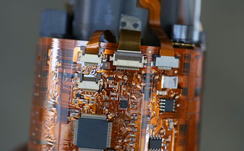
Space Efficiency: Rigid-flex PCBs are highly space-efficient, as they eliminate the need for connectors and reduce the need for additional interconnects. They can be folded or bent to fit within tight spaces, making them ideal for compact and densely packed electronic devices.
-
Reliability: Fewer connectors mean fewer potential points of failure, improving overall system reliability. Rigid-flex PCBs are less prone to connector-related issues.
-
Durability: Rigid-flex PCBs are designed to withstand mechanical stress, vibrations, and temperature variations, making them suitable for applications in harsh environments.
-
Reduced Assembly Costs: Despite the initial complexity of manufacturing, rigid-flex PCBs often result in reduced assembly costs due to fewer components and manual assembly steps.
-
Complex Geometries: Rigid-flex technology enables the creation of complex board shapes and three-dimensional configurations that are challenging to achieve with traditional PCBs.
What Are the Challenges in Designing Rigid-Flex?
-
Complex Design Rules: Rigid-flex PCBs often have more complex design rules compared to rigid PCBs. Designers need to understand the mechanical and electrical requirements of both rigid and flexible sections, including bend radii, layer stackup, and material constraints.
-
Bend Radius Considerations: One of the critical aspects of rigid-flex design is determining the appropriate bend radius for the flexible sections. Choosing a bend radius that's too small can lead to mechanical failure and signal integrity issues.
-
Material Selection: Selecting the right materials for both the rigid and flexible portions of the PCB is crucial. Different materials have varying thermal expansion coefficients, which can lead to reliability problems during temperature variations.
-
Signal Integrity and EMI: Maintaining signal integrity and controlling electromagnetic interference (EMI) in the flexible sections can be challenging. The flexibility of the substrate and the proximity of signals to the bend region can affect signal quality.
-
Connector Placement: Deciding where to place connectors to transition between the rigid and flexible sections is a critical design decision. Poor connector placement can lead to mechanical stress and reliability issues.
-
Layer Transition: Properly transitioning signal layers from the rigid to the flexible sections can be challenging. Misalignment or improper layer transitions can result in impedance mismatches and signal degradation.
-
Thermal Management: Managing heat dissipation in rigid-flex designs can be more challenging than in traditional rigid PCBs. The flexibility of the substrate may limit the use of traditional heat-sinking methods.
-
Assembly and Manufacturing: The assembly process for rigid-flex PCBs can be more complicated than for rigid boards. Designers must consider how the board will be assembled and ensure that components can be placed and soldered correctly.
-
Testing and Inspection: Inspecting and testing rigid-flex PCBs can be more challenging due to their complex, three-dimensional nature. Specialized testing equipment and procedures may be required.
-
Mechanical Reliability: Ensuring that the flexible sections can withstand repeated bending and flexing without mechanical failure is essential, especially in applications like wearables or foldable devices.
-
Cost: Rigid-flex PCBs can be more expensive to manufacture than traditional rigid boards due to the complexity of the design, materials used, and manufacturing processes.
-
Design for Manufacturability (DFM): Achieving good manufacturability in rigid-flex designs can be difficult. Designers must consider the capabilities and limitations of the manufacturing processes and work closely with fabricators to ensure a successful build.
-
Environmental Factors: Rigid-flex PCBs may be exposed to harsh environments in applications like automotive or aerospace. Designers must consider factors like moisture resistance, corrosion protection, and thermal cycling.
-
Design Verification: Rigorous testing and verification processes are essential to ensure that the final rigid-flex PCB meets all specifications and performance requirements.
Addressing these challenges requires an understanding of both electrical and mechanical engineering principles, as well as collaboration between design teams, fabricators, and assemblers. Proper planning, simulation, and testing throughout the design process are crucial to achieving reliable and functional rigid-flex PCBs. Keep an eye out for future blogs addressing each of these rigid flex design challenges!
Whether you need to build reliable power electronics or advanced digital systems, Altium Develop unites every discipline into one collaborative force. Free from silos. Free from limits. It’s where engineers, designers, and innovators work as one to create without constraints. Experience Altium Develop today!
