
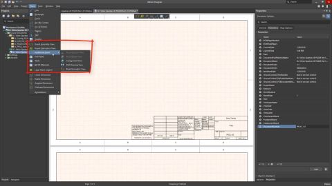

The Multi-board Schematic editor provides a range of graphical element tools that can be used to place basic, free-form drawing elements in a multi-board schematic sheet. The type of graphical tool to be placed can be selected from the Place main menu. Place a graphic element by clicking to position its first node/point and then again to place following nodes, therefore determining its size –…
The following sections list historical release notes for Public releases of Altium Designer (from version 25 down to 20.0). For the latest release notes for Altium Designer, Altium Designer Develop and Altium Designer Agile, visit the Public Release Notes page. Looking for public release notes for all previous versions of Altium Designer? Visit the Legacy Documentation section of the Other…
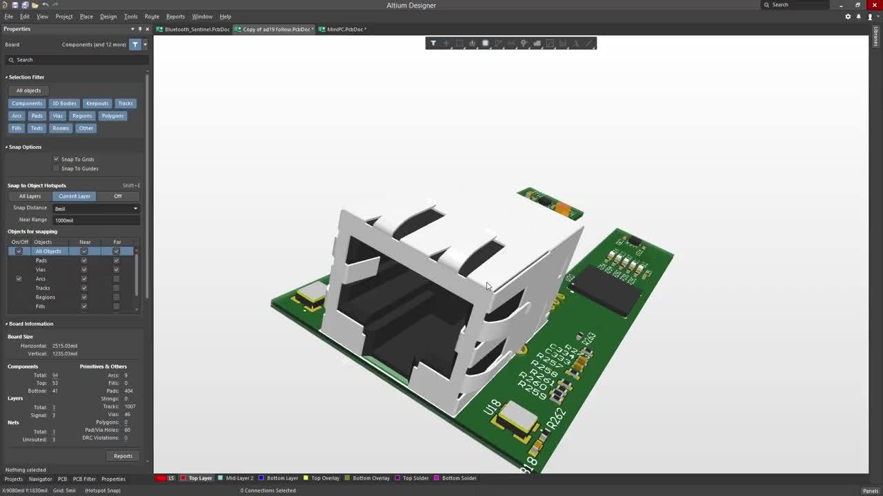
When you first transfer the boards into the multi-board assembly editor, they are neatly placed on the same plane – you can imagine them as all being laid out next to each other on a virtual table. Within a few minutes, you will have moved this one, rotated that one, and pulled another one closer to you! And then you will have rotated the view, now you are not even sure which way is up! Working…
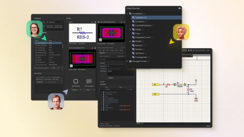
The Design Reuse panel that is used to manage snippets and described on this page is in Open Beta and available when the UI.ModernDesignReusePanel option is enabled in the Advanced Settings dialog. When this option is disabled, the previous iteration of the panel described on the Working with Reuse Blocks & Snippets page is used. The snippets feature allows you to save any selection of circuitry…
When UI.ModernDesignReusePanel is in the Public state - update the blue box below with the source code of the 'Open Beta Feature Moves to Public' snippet. The Design Reuse panel that is used to manage reuse blocks and described on this page is in Open Beta and available when the UI.ModernDesignReusePanel option is enabled in the Advanced Settings dialog. When this option is disabled, the previous…
A Draftsman board fabrication view (Place » Board Fabrication View) is an automated graphic composite of the PCB project's unpopulated (bare) board, as viewed from the top or bottom. The drawing data is sourced from a specified physical board layer, and additional layers can be shown as required. Two placed board fabrication views that show the top and bottom layers of the PCB For even greater…
Altium Designer, in conjunction with the Altium 365 Workspace, brings support for an advanced project construct that targets the development stage of the project lifecycle, simplifying the creation and ongoing workflow for version-controlled projects. Centralized storage under the control of the Workspace also enables this feature to be a foundation for other collaborative services. Some key…
Altium's MCAD CoDesigner technology connects the mechanical and electrical design domains, allowing the mechanical and electronic engineers to pass the loaded PCB back and forth between the two domains. In your Altium design software, this is achieved through an extension that loads and extracts board and component data from the PCB editor, the MCAD CoDesigner extension. In the MCAD software the…
Release Notes Release Notes for Altium Designer 15.1 Release Notes for Altium Designer 15.0 Historical Release Notes QuickLinks Exploring Altium Designer Altium Designer - Features Altium Designer 15.1 Released: 8 May 2015 - Version: 15.1.9 Released: 2 June 2015 - Version: 15.1.12 Released: 2 July 2015 - Version: 15.1.13 Released: 22 July 2015 - Version: 15.1.14 Released: 14 September 2015 -…
The following sections list the release notes for publically released versions of Altium Designer 15.1 and Altium Designer 15.0 For a summary of new features and enhancements in Altium Designer 15.x, see New in Altium Designer. For a listing of release notes for versions of the software prior to 15.0, see Historical Release Notes. Version 15.1.16 Build: 63332 Date: 2 June 2016 7492 Restored the…
Learn More