The Best Power Supply Circuit Design Tools With Simulation

From bench-top power supplies to power regulator circuits on embedded boards, designers often need to create a custom power supply circuit design and layout. These circuits sound simple to design, but it takes the SPICE-based simulation and verification tools in Altium Designer to create a stable, high-quality power supply circuit design.
Altium Designer gives you much more than circuit design and circuit simulation tools; you can easily create your PCB layout and prepare your board for manufacturing in Altium Designer. Keep reading to see how our circuit design software helps you create the best power supply circuit design and layout.
ALTIUM DESIGNER
A unified PCB design package that integrates circuit design features with a powerful PCB editor and simulation features.
It’s easy to design a simple voltage regulator, but production-grade power supplies go far beyond linear regulators. Power supply circuit design for your PCB can get very complex, and multiple tools are required to create your schematics, PCB layout, simulations, and manufacturing files. After you determine the best regulation and power conversion topology for your system, you’ll need to implement your circuits in schematics and verify your design.
When you have access to an integrated design package, you can design your power supply schematics, create a high-quality PCB layout, and run circuit simulations in a single program. Keep reading to see how the best set of circuit simulation and design features can help you create and simulate your power conversion and regulation strategy.
Choose a Regulator and Power Conversion Strategy
Power supply circuit design requires considering the entire system in blocks, starting from an AC to DC converter circuit, and onto power conditioning and power converter stages. Some voltage or current regulator topologies can provide multiple functions throughout the power conversion process. However, these regulators can be very complex and must be validated with simulations before proceeding to manufacturing.
The figure below shows an example block diagram that includes all the critical portions of a power supply. This type of system is meant to provide high-efficiency power conversion with a switching regulator. It could receive wall power and convert AC to DC with a bridge rectifier. The rectifier output would then be passed to a PFC circuit, which will smooth out current spikes from a switching converter. The input and output would then be filtered to remove conducted EMI and ensure stable power is passed to regulator sections.

Power supply circuit design stages and converter block diagram.
The regulator section then needs to be designed with the appropriate topology. The most common regulator topology is a switching regulator, giving an SMPS power supply. These power supplies can be designed to provide very stable output voltage and high-efficiency regulation. They also have many well-known topologies for DC-DC conversion.
|
Topology |
Efficiency |
Advantages |
Disadvantages |
|
Linear |
Low (~60%) |
Simple to build |
High headroom, low efficiency |
|
LDO |
Low (~60%) |
Low headroom (~1 V), can be used on the output stage to get to the desired voltage |
Low efficiency |
|
Buck |
>85% |
Simple to build |
Switching noise, conducted EMI propagates to the output |
|
Boost |
>85% |
Simple to build (variant of buck converter) |
Switching noise, conducted EMI propagates to the output |
|
Flyback |
>85% |
Flexible: operates as buck or boost converter, galvanic isolation |
Higher cost, requires stable input power, switching noise |
|
Forward |
>85% |
Flexible: operates as buck or boost converter, galvanic isolation without saturation |
Higher cost, requires stable input power, switching noise |
Create Any Regulator Topology With the Best Schematic Design Tools
Creating the regulator topology you need to ensure high-efficiency power conversion requires the best set of schematic design tools. You’ll also need access to a complete set of PCB components that include CAD models for use in your PCB layout. When you’re ready to start your power supply circuit design and find the components you need, use the complete set of PCB design tools in Altium Designer.
- High voltage/high current power supply design often requires placing a PFC circuit after your AC to DC converter circuit to smooth out current spikes on the input.
- When designing your switching regulator circuit, make sure you choose the right frequency for your PWM signal as this will influence efficiency and ripple on the output voltage and current.
Learn more about selecting the best frequency for your switching regulator.
- Your power supply may need to be isolated with a transformer to ensure user safety.
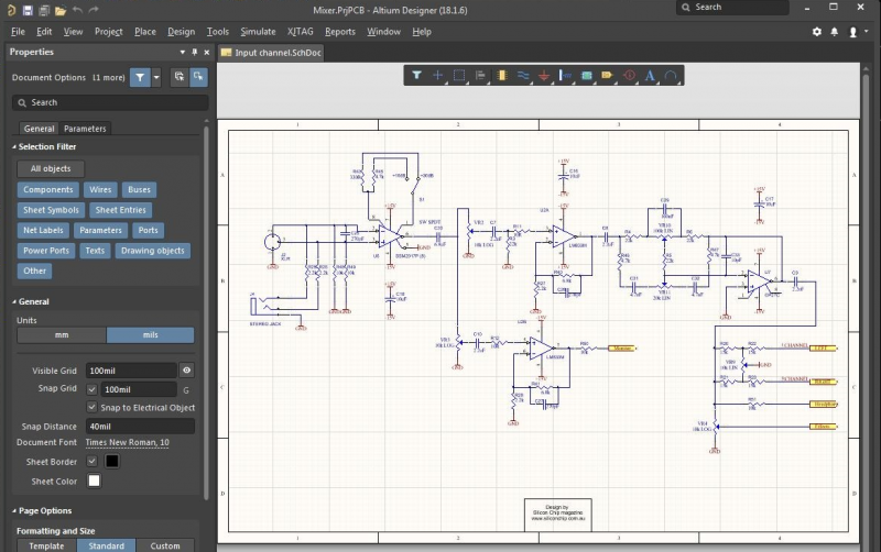
Create each section of your power supply circuit design with the hierarchical multichannel schematics tools in Altium Designer.
Integrated Simulation for Power Supply Circuit Design
Because of safety and operational concerns around many power supplies and regulator circuits, there is a need to simulate each section of a power supply to ensure it provides the desired electrical behavior. Simulating a power supply requires a SPICE simulation that takes component data and subcircuit models directly from your schematics. This type of simulation then solves Kirchhoff’s Laws and Ohm’s Law to ensure your circuit design will operate as intended.
SPICE simulators allow you to perform some critical simulations as part of power supply circuit design:
- Transient analysis to see the voltage, current, and power output in the time domain
- Noise analysis to examine how input noise is transformed into output noise
- AC analysis with frequency sweeps in each section of the power supply
- Parameter sweeps to iterate through multiple circuit values and optimize the design
Transient analysis will be used most often as this type of simulation shows how the power supply starts up and reaches its operating state in the time domain. You can then determine which portions of the system need to change, and you can iterate through trial values for your circuit elements with parameter sweeps. These tasks don’t require an advanced simulation package, you can perform these simulations and many more in the industry’s best PCB design software.
Use Altium Designer for SPICE Simulations
The SPICE simulation engine in Altium Designer is accessible inside the schematic editor, and it will take data directly from your component libraries and models. These simulations are easy to set up and run, and data can be saved for use in an external analysis program like MATLAB. The parameter sweep tools are ideal for optimizing your power supply circuit design, and these tools will output multiple results that can be compared on a single graph.
- Filter circuits are basic elements, but they are very important for power supply design as they will ensure your system can remain immune to input noise.
Learn more about EMI/EMC control with power supply filtering.
- Pay attention to any noise that is generated or received in your regulator circuit to ensure it is not excessive in the power supply output.
Learn more about analyzing noise margin in your power supply.
- Power supply circuit design requires SPICE simulation to ensure the output power is stable and reaches the desired value.
Learn more about running SPICE simulations with power supply circuits in Altium Designer.
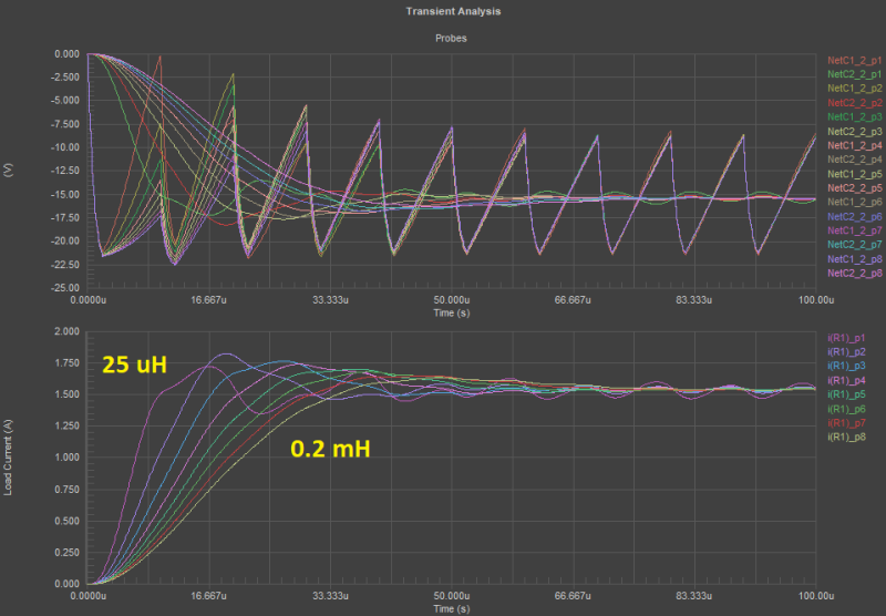
The SPICE simulator in Altium Designer helps you verify your power supply circuit design and optimize its power output.
Create a PCB Layout for Your Power Supply Design
Once you’ve created your power supply circuit design, it’s time to capture your schematics as a blank circuit board layout. You can then start arranging components, routing traces, designing power planes, selecting ground planes, and much more. Your PCB layout will determine the thermal management measures you’ll have to consider to keep the circuit board temperature low, and you’ll need to source real components for all the parts in your design.
Altium Designer is more than just circuit design and simulation software, it’s the industry’s most powerful PCB design application for product development. Power supply designers will have access to a complete set of PCB design tools for schematics, physical layout, simulation, and PCB manufacturing, and all in a single program. Everything needed to produce a high-quality power supply is included in Altium Designer’s rules-driven design environment.
Most design programs force you to use separate schematic editors, routers, and simulators to produce a single product. This makes for an inefficient workflow and even forces you to use 3rd party design tools to complete a new design. Instead of working in this type of fragmented environment, you need to create your next SMPS circuit board in a unified design package.
When you work with unified design software, you’ll have access to everything you need to create a new product in a single application. This is the type of environment you’ll find in Altium Designer. Everything you need is in a single application, allowing you to go from concept to product with ease.
Finish Your Power Supply Design With the PCB Layout Tools in Altium Designer
Altium Designer’s major advantage over other PCB design platforms comes from its integrated design interface, where everything you need for power supply circuit design and layout is included in a single program. Instead of placing everything in separate programs, Altium Designer includes a complete set of features you need to complete your PCB layout and prepare it for manufacturing. No other PCB design application makes it this easy to take a new product to market with a single program.
- Designing your power supply circuits, placing components, and routing traces are easy tasks in Altium Designer. The rules-driven design environment in Altium Designer instantly checks your layout against design rules as you create your circuit board.
Learn more about the integrated design environment in Altium Designer.
- The powerful routing and layout tools in Altium Designer are key to your productivity and will help you stay within your mechanical requirements.
- Once you’ve created your power supply circuit design and performed circuit simulations, you can share your project and simulation data with your team through Altium 365.
Learn more about sharing your PCB project data with Altium 365.

The complete set of PCB power supply design features in Altium Designer.
You shouldn’t have to use separate programs for PCB layout, simulation, and circuit design to build your next power supply. You can create power supply circuit designs with any topology using the best circuit design software and layout tools in Altium Designer. No other application gives you the same level of support or productivity as Altium Designer.
Altium Designer on Altium 365 delivers an unprecedented amount of integration to the electronics industry until now relegated to the world of software development, allowing designers to work from home and reach unprecedented levels of efficiency.
We have only scratched the surface of what is possible to do with Altium Designer on Altium 365. You can check the product page for a more in-depth feature description or one of the On-Demand Webinars.

