What Types of EMI Filters are Best for Passing EMC Testing?

When you need to pass EMC testing and your new product is being crippled by a mysterious source of EMI, you’ll probably start considering a complete product redesign. Your stackup, layout/routing, and component placement are good places to start, but there might be more you can do to suppress specific sources of EMI.
There are many different types of EMI filters that you can place in your design, and the right filter can help suppress EMI in a variety of frequency ranges. These circuits can be of the passive or active variety and provide different levels of suppression in different bandwidths. The best choice of EMI filter for your design depends on a variety of factors, ranging from space on your board to the required attenuation. In addition, some filters are relatively broadband (e.g., op-amps), while other circuits can only target narrow frequency ranges.
Types of EMI Filters
All EMI filters can be classified as passive and active filters, where each type is constructed with passive or active components, respectively. Going deeper, these different types of filters target specific types of noise: either common-mode or differential-mode. Obviously, these circuits can be cascaded to provide filtering of both types of EMI. When you're trying to correct an EMI problem, including after failed EMC testing, you may need to implement multiple solutions beyond filtering.
Let’s run through the common types of EMI filters falling into each category:
Passive EMI Filters
Differential-mode Passive EMI Filters
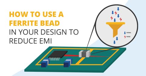
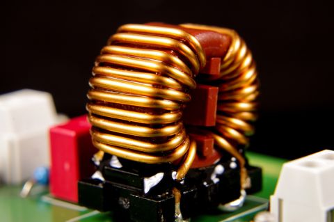
Perhaps the most common passive EMI filter is a ferrite choke. This is basically an inductor with some parasitic capacitance that provides low-pass filtration up to several tens of MHz. These components can provide filtration of common mode or differential mode conducted EMI. If you’re reading this on a laptop, then your power cord probably uses one of these chokes to remove high frequency noise on the input power line. When you look at the PCB, there are several other circuits you can use to provide filtration.
The image below shows a collection of LC circuits used as differential-mode passive EMI filters. These filter circuits are differential-mode circuits because, physically, we would only have a single reference for the return path. An example here would be a device powered with 2-wire DC voltage, such as with a bench PSU or a battery. Note that there may be a floating or grounded chassis nearby, but in the below circuits, it does not participate directly in conducting current and has perfect isolation from the rest of the system.
The simplest of these filters are C filters (connected as shunt capacitors) and L filters (connected as series inductors). These can be placed in a critical circuit or on the input of a critical component in order to remove noise at a broad range of frequencies. More complex configurations are shown in the image below. Regarding the Pi and T filters, these are best used with low and high-source/load impedances, respectively.

If you need to pass your desired signal into a component while suppressing all other frequencies, then you need to build a bandpass filter. Similarly, you may want to suppress a strong signal at a single frequency (such as stray emission from an antenna), which would require a bandstop filter. Note that the number of L/C elements in the circuit determines the filter number; building a higher order (i.e., cascaded) filter will provide steeper roll-off outside the passband.
Common-Mode Passive EMI Filters
The above list of EMI filters can be built as common-mode filters by bringing in an additional reference conductor. As is well-known, common-mode currents are induced via parasitic capacitance to an outside reference, such as metal in the chassis or some external conductor (i.e., via a ground loop). Common-mode currents can also enter a system via its power lines, e.g., via the output from a switching DC power supply or from AC mains.
To deal with common-mode noise, you have three potential options you can use on a differential line:
- Use a high-impedance element in series on the line, namely a common-mode choke
- Use a low-impedance shunt element back to the system reference (usually chassis or back to earth)
- Modify the layout to eliminate capacitive coupling
The image below shows an arrangement where we've satisfied points 1 and 2. The EMI filter circuit below applies to an AC mains input, or to a 2-wire DC input (+V and DC common) with an earthed wire connecting to the chassis. This circuit contains two separate elements: a common-mode choke and a low-pass filter via a pair of capacitors.

Active EMI Filters
Active filters are the transistor-driven analog of passive filters. These filters use op-amps and passives to provide filtration in the desired bandwidth. These filters can also be constructed as higher order filters to provide steep roll-off with relatively flat passbands or stopbands. Any of the equivalent fundamental filters can be built with op-amps, and these filters are sometimes integrated into SoCs or other specialty ICs for particular applications. They can also be configured to suppress common mode and differential mode noise in a single circuit.
An example would be the above schematic with the common-mode choke and pair of capacitors connected to an op-amp. The transfer function of the amplifier can then be adjusted by adding reactive elements to the feedback loop, although watch out for the stability of this type of active EMI filter circuit. This area of the field of electronics design is quite broad and is covered in many textbooks. One great textbook on this subject is Manual of Active Filter Design by John L. Hilburn.
Going Further to Microwave and mmWave Frequencies
EMI/EMC testing and compliance in this regime is more complicated, as are the devices being designed and tested. When EMI from a product under test is a major problem, or when EMI within a product is difficult to solve, there are more advanced design choices to consider beyond the points mentioned above. Absorbing conformal coatings can help provide additional isolation, particularly for EMI from the board edge at GHz frequencies. Unique isolation structures can also go a long way toward suppressing radiated EMI between different circuit blocks in a product, as well as provide additional isolation from external EMI. Best practices for RF layout/routing, stackup design, and unique RF interconnect architecture will go a long way towards suppressing EMI emission and reception from these types of products.
No matter which types of EMI filters, interconnect geometry, or isolation techniques you use, you should simulate their effects on signal integrity using pre-layout and post-layout simulation tools. Pre-layout SPICE simulations are ideal for qualifying EMI filter designs and ensuring your filter provides the right level of attenuation within the desired bandwidth.

When to Use EMI Filter Circuits
One important point that should be considered is what actions to take when a design is not passing EMC testing. Whenever I've been asked by a client to rework one of their designs due to failed EMC testing, the solution doesn't always require filtering circuits. Sometimes the problem is proper grounding on the board and in the enclosure, or the solution can involve re-working a specific circuit in addition to adding EMI filtration.
- Start with the layout and grounding. Whenever I get asked to fix a phantom EMI problem that causes EMC testing failure, the first place I look is split reference planes used for digital routing and improper switching between reference planes in a multilayer board.
- If you've done everything with grounding and routing correctly, and you still have some EMI problem, the issue may require adding a new EMI filter, or redesigning an existing EMI filter. For common-mode noise, you may need to reconsider how you've grounded the system to prevent capacitive noise coupling into the PCB.
- The above two steps primarily target conducted EMI entering or leaving a system, as well as any radiated EMI produced by conducted currents. If you've used EMI filters and implemented best layout practices for your board, and you're still observing strong radiated EMI, then you might need to get more aggressive and add board-level or enclosure-level shielding.
Beyond the above points, EMI filtering might be mandatory for some systems. Two examples are in precision measurement and control systems that interface with low-level analog signals, or in high power systems that connect to the grid. Consider these points and the particular EMI sources before you start adding filter circuits to every interface in your system.
If you opt to use EMI filter designs or more aggressive tactics like board-level shielding in your board, use the design tools in Altium to create your physical layout and prepare your design for manufacturing. You can use the EDB Exporter extension to import your layout into Ansys field solvers and pinpoint EMI problems in your design. When you’re ready to send your design our for fabrication and assembly, you can easily release your design data to your manufacturer with Altium.


