


Configuring a Hardware in the Loop Project

At a Glance
This article will walk through an example project of a board designed in Altium Designer and run through a DevOps flow using hardware in the loop testing against its firmware.


In Hardware in the Loop Testing: An Introduction, we reviewed what hardware in the loop testing (HIL) is, how a setup would look, and why we would want to integrate this into our project design. This article will walk through an example project of a board designed in Altium Designer and run through a DevOps flow using hardware in the loop testing against its firmware.
Design
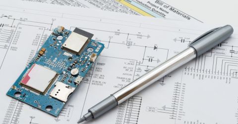
Before setting up any hardware in the loop configuration, we need a board to work on. A good way to get started with a design before schematic capture and layout is to prototype with evaluation boards. The evaluation board we will be using for this article will be the SAM4E XPlained Pro from Microchip (formerly Atmel). To get started, you will need this evaluation board, and also Atmel Studio installed. Once you have your hardware and software up and running, you can clone the sample project from Gitlab. This example project contains a minimal amount of code - just enough to demonstrate the hardware capabilities in the loop testing. This project also leverages some libraries from the Atmel Software Framework (now renamed as “Advanced” Software Framework). The ASF provides drivers that enable USB serial communication, delay routines, and other libraries that abstract many low-level hardware implementations normally written for other microprocessors. Once you have pulled the repository, compiled, and loaded the firmware, you are now ready to set up and run hardware in-the-loop testing.
Configuration
For version control and continuous integration/continuous deployment (CI/CD), Gitlab has been chosen as the host. As demonstrated in How to Create a CI/CD Pipeline for Your PCB Design, version control and CI/CD are integrated as one tool in Gitlab. This project consists of multiple CI/CD stages (also known as “Pipelines” in Gitlab):

The first stage creates the binaries needed to load the programming files on the microprocessor. After this is done, the downstream device (i.e., the evaluation board) is powered on. The device is then programmed, and the unit is now ready to be tested.
Test
Hardware in the loop testing can be as simple or as complex as you design it to be. While many complex HIL systems require external devices to emulate real-world environments, this example uses a basic mechanism to emulate an external stimulus: serial communication. Atmel's USB Device CDC interface creates a virtual COM port to enable communication over USB just as you would with UART via RS-232. In this suite of tests we:
- Set a register by sending a command
- Read the register (to validate our command)
- Clear the register
- Read the register once more
While the firmware for the microprocessor is written in C, the test software (that drives the commands and reads the telemetry) is written in Python using the Pytest framework. Writing the software in Python allows us to take advantage of high-level scripting and libraries that would normally require much more time and effort to develop in a compiled language such as C++. Additionally, we can run these tests on any type of machine agnostic of its operating system or even chip architecture. The same tests that run on a Windows PC (Windows, x86) can also run on a Raspberry Pi (Linux, ARM). Abstract development, compiling, and testing from your machine is a key principle in the DevOps workflow. We want to be able to reproduce a new environment at the snap of a finger. Moreover, we want to avoid the painstaking hours it takes to spin up a development environment by reading pages and pages of “How to” or “Getting Started” guides. Scripting this process (including the testing), as has been done in the pipeline definition file, ensures a reproducible environment without the fuss. To run the same tests manually from the command line, see the pipeline file.
After the test completes, the results are written to a JUnit XML file which is then parsed by Gitlab and displayed in the web interface.

We now have demonstrated a full end-to-end solution of hardware in the loop configuration with Gitlab. Feel free to peruse around the project to get more acquainted with the setup and format.
Conclusion
In this article, we reviewed how to configure your project for hardware in the loop testing. This included an example project hosted on Gitlab that users can clone and configure using the pipeline configuration file (i.e., .gitlab-ci.yml file). We also covered running the tests in Python using the Pytest framework and discussed how it is displayed in the web interface. The user now has the ability to create their own hardware in the loop setup using this guide and the sample project hosted on Gitlab.
Would you like to find out more about how Altium can help you with your next PCB design? Talk to an expert at Altium and learn more about making design decisions with ease and confidence.
About Author
Related Resources
Related Technical Documentation
Table of Contents
Design to Release, Without the Friction
- Keep reviews tied to the right version
- Reduce handoff confusion and rework
- Spot sourcing and release risk earlier
- Work solo, share when needed
Get Started
Thank you, you are now subscribed to updates.