
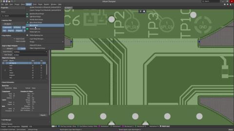

This article shows you how to measure distances accurately in an Altium Designer PCB document, covering the available measurement tools in both 2D and 3D modes. You will get a practical overview of how to measure between points, primitives, selected tracks and arcs, and 3D objects or faces, while also understanding how cursor snapping affects precision and how measurement results are displayed,…
This article walks you through how tracks work in Altium Designer, from basic placement and editing to interactive routing behavior and rerouting existing connections. It explains the difference between tracks used for electrical routing and lines used for drawing, shows the key placement actions and shortcuts, and outlines how design rules such as clearance and routing width affect what happens…
This article explains how Altium Designer’s Board Insight system helps you make sense of dense, multi-layer PCB designs by giving you better ways to view, identify, and interact with objects in the design space. It walks through the core features, including pop-up inspection tools, the Visual Pick List, the Heads Up Display, live net highlighting, active layer control, net name display, pad and…
This article shows how to control object and layer transparency in Altium Designer using the View Configuration panel and Object Visibility dialog. It walks through setting transparency globally, by object type, and per layer, explains how the dedicated Altium Transparent 2D view works, and highlights practical ways to fine-tune visibility so you can better inspect your PCB design. If you want a…
This article explains how grids and guides work in Altium Designer’s PCB editor, showing how snap grids control object placement, how multiple grids can be defined and prioritized, and how snap guides help with visual alignment. It also highlights when metric or imperial grids make sense, and introduces the Grid Manager tools used to configure user-defined Cartesian and Polar grids for more…
Bridging the ECAD-MCAD Divide The electronic product you hold in your hand is the melding of numerous, independent designs. Firstly there's the enclosure you're holding; inside that, there will be one or more electronic circuit boards, and on the board, there is often a microprocessor running software. Beyond that, there can be specialized sections of circuitry to perform unusual sensing or…
The Company Dashboard Authentication page allows Company Account Administrators to configure and enable Single Sign-On (SSO) capabilities for your Company Account and includes support for SCIM (System for Cross-domain Identity Management) user and group provisioning, which automates the exchange of identity data between your company and its Identity Provider (IdP). This backend configuration…
What do SOLIDWORKS PCB and SOLIDWORKS PCB Connector end-of-life mean? Starting August 15, 2023, SOLIDWORKS PCB and SOLIDWORKS PCB Connector will no longer receive updates or support. Will SOLIDWORKS PCB or SOLIDWORKS PCB Connector still be supported? SOLIDWORKS PCB and SOLIDWORKS PCB Connector will be supported through August 14, 2023. Will I need to export all the files from the solutions before…
Altium CoDesigner brings the electronic and mechanical design worlds together. With this comes the challenge of defining design object and spatial requirements in different design domains, and different design languages. This series of videos will help in the process of understanding how best to transfer your design between the mechanical and electronic design domains. The videos on this page…
How MCAD CoDesigner supports Harness Design MCAD CoDesigner’s Harness support integrates the ECAD and MCAD models of the harness. The goal is to allow the harness geometry to be designed in MCAD and then transferred back to ECAD, as the physical parameters (lengths) of the harness elements. The common (and essentially similar) element between the ECAD and MCAD environments is that the schematic…
Learn More