Everything You Need To Know About Impedance

The term impedance is used in many different contexts like transmission lines, loudspeakers, and basic electrical components. At school, we were all taught about the impedance of inductors using the general physics of electricity. Still, if engineers have not worked with real impedance problems in PCBs or electrical components, its practical meaning may not be clear. It is easy to get confused without understanding where impedance originated and hearing it is used in many different contexts. In this article, I go through the basics of impedance.
Z = U/I
Basically, impedance is not complicated. It does not matter what the context is where the term impedance is used because, in all cases, it has precisely the same meaning: it is the relationship between the voltage and current. It differs from the resistance by having frequency dependence, whereas resistance is constant in all frequencies. If your signal is pure sine for the impedance of the inductor, you are interested in knowing the impedance at the sine signal frequency. If your signal impedance is digital, you are interested in knowing the impedance from DC to the signal's highest frequency. When analyzing the impedance and voltage divided by the current calculation, you need to consider the frequency. Impedance is voltage divided by a current at a specific frequency. Because of the relationship between voltage and current, the unit of impedance is the ohm.
Reactive Elements
Basic electrical reactive elements are capacitance and inductance. I don’t use the terms capacitor and inductor because these relate to real physical components, and now we are considering the ideal phenomena only. These two ideal “components” have an impedance that depends on the frequency. This means that with constant voltage, the current flowing through the component changes with the frequency because the impedance of inductor changes with frequency. For example, an ideal capacitor has a typical impedance as in Figure 1. Impedance is high at low frequency but gets smaller when frequency gets higher. If we want to get current through the capacitance to be the same in both low and high frequencies, we need to add higher voltage when the signal operates at low frequencies and smaller voltage at higher signal frequencies.

Figure 1. Ideal capacitor impedance. Both the x-axis & y-axis are logarithms
Inductance has the opposite behavior. Its impedance is low at low frequencies and increases with higher frequencies as shown in Figure 2. These two reactive elements determine the impedance of all electrical circuits and components. The impedance of inductor is always a consequence of capacitances and inductances.

Figure 2. Ideal inductor impedance
(R)CL Circuits
In practice, all real-life impedances are consequences of different combinations of series or parallel connected inductances and capacitances. Together these two components create impedances that depend on whether the capacitance and the inductance are connected in parallel or series as shown in Figure 3.


Figure 3. The impedance of parallel (green) and series (red) connected capacitance and inductance.
When capacitance and inductance are in series, the impedance is high at low and high frequencies, and the minimum point is somewhere between these. In the case of parallel connection, we see impedance is low in both low and high frequencies but gets high in the middle. In LC circuits, decreasing impedance comes from system capacitance, and increasing impedance comes from the system inductance. Both low and high impedance peaks are resonance frequencies that capacitance and inductance together create. At the resonance frequency, impedance gets its extreme minimum or maximum value, and resonance frequency depends on the capacitance and inductance, according to the equation below.
Fresonance = 12πLC
In Figure 3, capacitance is 1nF and inductance is 100nH, which gives a 15.9MHz resonance frequency.
If the CL circuit includes resistance, which is constant for all frequencies, it sets the minimum impedance level at a resonance frequency. For example, suppose we add the ideal 10Ω resistance in series with 100nH inductance and 1nF capacitance. In that case, we get a similar impedance profile, but the minimum impedance level is 10Ω, as we can see in the simulation results in Figure 4. Please note that in real life, we rarely see impedances like those presented in the green graph of Figure 4 because resistive elements have their parasitics which provide a lower impedance path for high frequencies. Nevertheless, in practice, all impedances in real life are composed of series or parallel connected capacitances, inductances, and resistances.

Figure 4. The impedance of parallel (green) and series (blue) connected RCL circuits.
Real Components
Each component has capacitance, inductance, and resistance. We can model the equivalent circuit of each electrical component by parallel and series-connected inductances and capacitances. In many cases, circuits also contain resistance elements, for example, due to the ESR of capacitors. Figure 5 is an example of an SMD resistor equivalent circuit.

Figure 5. Equivalent circuit of a real resistor. Image from www.vishay.com
A simple resistor has reactive components because the component terminals have inductances, and the resistive element has parallel capacitance. Thus the impedance of the resistor is not constant but becomes more frequency-dependent at high frequencies as shown in Figure 6. The resistive element of the resistor is constant, but parasitic elements cause its frequency-dependent impedance. Because components’ parasitic capacitances and inductances are dependent on physical parameters, like terminals of a component, the physical dimensions have a significant impact on the impedance of the component. The bigger the physical size of a component, the more significant its parasitic capacitance and inductance become, which directly impacts system impedance. The same principle applies to all electrical components, and the equivalent circuit depends on the specific component.

Figure 6. The impedance of real resistor. Image from www.vishay.com
Real Traces
Every time we design traces on a PCB, we design inductances and capacitances. The trace has always inductance due to the current loop and capacitance due to the physical separation of the trace and its reference plane. Again, it is good to notice that the trace dimensions and its geometry in relation to the reference plane determine the capacitances and inductances, thus the trace's impedance. Designing trace impedance requires designing trace dimensions and electrical circuit layouts in 3D. This is the reason why some layouts work better than others, even if they have the same function: the layout geometry is different.
Let’s take the example of simulations of a couple of different PCB traces. In this PCB, we have three straight traces. Two of the traces have no reference plane beneath, and their lengths are Trace 1, 35mm, and Trace 2, 120mm. The third trace has a solid reference plane beneath, and its length is identical to trace 2, 120mm. According to the Altium Designer, stack-up tool’s impedance calculator, the impedance of trace 3 is 50Ω. Traces and their stack-up are presented in Figure 7. Trace simulations were made using CST, and at first, I simulated the s-parameters of each trace by adding ports for each trace. Then I drove these traces by 50Ω source while the end of traces was terminated by 50Ω resistors.


Figure 7. Simulated traces and PCB stack-up. Dimensions are in millimeters.
In Figure 8, you can see the simulation results of traces without a solid reference plane beneath. We see impedance starts increasing when frequency increases, and we also see it is the length of trace which determines the frequency when impedance starts increasing. These kinds of traces have relatively big inductance and low capacitance which leads to this impedance behavior.


Figure 8. EM Impedance simulations of two traces without reference plane
In our second simulation example, we compare two 120mm traces, but one has a reference plane, and another one does not have it. From the simulation results in Figure 9, we see the impact of the reference plane; it makes the impedance constant. The capacitance increases because of the nearby conductive reference plane, but inductance drops because the current loop becomes physically smaller when the return current travels below the trace. Adding a reference plane has changed our trace into a transmission line.
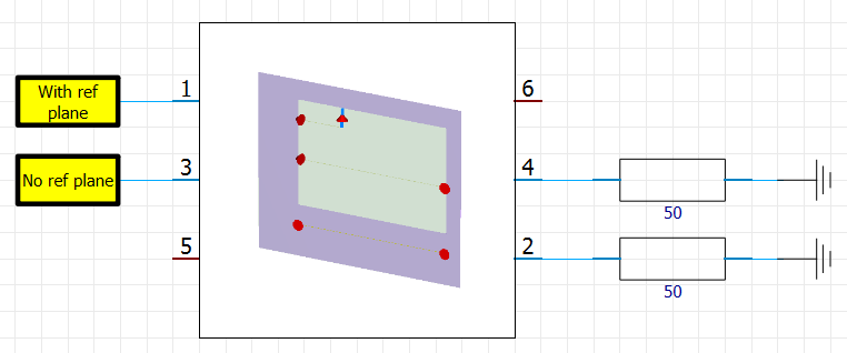

Figure 9. EM simulations of 120mm trace with and without reference planes
Transmission Lines
Probably impedance is mostly known in transmission lines. As seen in Figure 9, the characteristic impedance is constant and ideally does not change with frequency for transmission lines. Transmission lines are a smart invention of utilizing trace inductance and capacitance in the way that the result is constant impedance in a wide bandwidth. The constant inductor impedance is achieved by proper geometry of trace width in relation to the distance to the reference plane beneath the trace. This allows using signals having wide bandwidth, like high-speed digital signals. Without transmission lines, we must stay at low frequencies.
Transmission lines are also a consequence of inductances and capacitances. Transmission lines can be modeled as distributed inductors – capacitor pairs in which inductors are in series and capacitors are connected to the ground as shown in Figure 10.
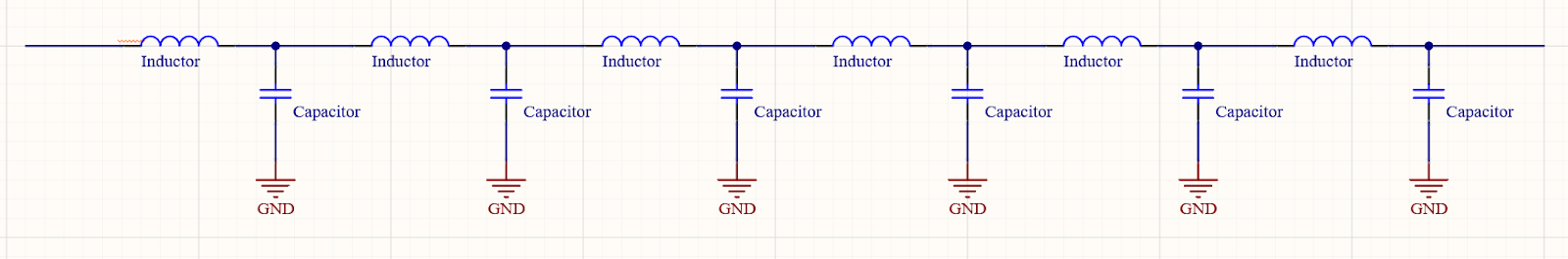
Figure 10. Transmission line equivalent circuit.
These distributed LC pairs create series and parallel connected resonance circuits having impedance minimum and maximum values constantly. The characteristic inductor impedance is then the square root of inductance divided by capacitance. The level of impedance can be adjusted by changing the width of the trace or adjusting the distance between the trace and the reference plane. This means we change individual capacitance or inductance elements. Also, dielectric material between the trace and reference plane impacts the capacitance in the same manner as it affects real capacitor capacitance. If you are designing transmission lines, Altium provides impedance simulation directly in the layer stack manager tool. With this, you can quickly check the impedance of the designed transmission line without EM simulation.
Conclusion: Impedance Comes From Geometry and Material Properties
Impedance is an important parameter in electronics design as it determines how components or interconnections modify the signal impedance. Inductor impedance originates from the physical dimensions of the electrical element, its distance to the current return path, and the electrical characteristics of the materials used. All of these contribute to parasitic capacitances and inductances for the electrical element and lead to the voltage-current ratio of the element becoming frequency-dependent.
Would you like to learn more about how Altium Designer® can help you with your next PCB design? Talk to an expert at Altium.

About Author
Related Resources


Table of Contents
Take advantage of the world's
most trusted PCB design system.
One interface. One data
model. Endless possibilities.
Effortlessly collaborate with
mechanical designers.
The world's most trusted
PCB design platform
Best in class interactive
routing
View License Options
Thank you, you are now subscribed to updates.