


Mechanics Meet Electronics Seamlessly in Multi-Board PCB Design


If you really take time to appreciate PCB layout, you'll find that circuit boards are as much a work of art as they are driven by science and engineering. Multi-board PCB design only expands the possibilities in terms of form, function, and capabilities. The reality is that many products are multi-board systems, and the need to integrate multiple PCBs into a single package or ecosystem is a specialized area of electronics development.
What makes multi-board systems more complex than working with a single PCB? It's not about the difficulty of the concept, but rather the fact that multi-board interconnects can be prone to errors. Furthermore, manual review and back-checking is time-consuming and, frankly, leaves a lot to be desired in terms of accuracy. Whenever this happens, the EDA industry steps in with a host of design and verification tools that can easily check connectivity in multi-board systems. If you have never seen these tools in action, here is a list of the big problems they solve both mechanically and electrically.
The Mechanical Side
Space Savings Without the Cost
Multi-board designs give you several interesting ways to make efficient use of the space available in your enclosure. Compared to another option, like a rigid-flex PCB, multi-board systems tend to cost less due to the lower cost of fabricating PCBs and the lower cost of board-to-board interconnects.
How can you achieve this space efficiency in multi-board systems? Here are some ideas:
- Board-to-board stacking with headers or mezzanine connectors
- Right-angle stacking along enclosure walls
- Board stacking using mechanical rails in the enclosure
- Low-profile interconnections using edge connectors
- Odd-angle stacking or interconnections using flex printed circuit (FPC) ribbons
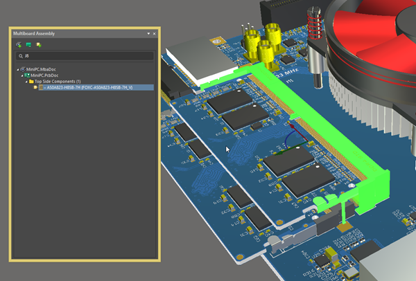
These stacking and interconnection techniques all require exploring the Z-dimension inside your enclosure. That means you need, at minimum, 3D visualization tools using standard 3D model formats for the PCB and its components.
What about error checking? Obviously, 3D design tools let you orient your boards any way you like, but how will you know that they fit together correctly and without mechanical interference? This is where it's time to loop in an MCAD engineer to take on these design tasks.
Work With Your Mechanical Engineer
Multi-board PCB design requires you to get out of your silo and work directly with a mechanical engineer. The mechanical engineer plays a very important role in multi-board systems design that goes beyond creating a housing. Their job extends to several important design tasks that will impact your electrical layout:
- Planning cable or wiring runs
- Planning the mechanical and electrical assembly order in the enclosure
- Determining openings in the housing for buttons, connectors, etc.
- Identifying collisions between components in the product
- Incorporating active or passive cooling elements
The most important part of product development in terms of mechanical design is form and fit within the enclosure, including as it relates to the assembly of multiple PCBs into a system. Closely related to the mechanical design is the electrical design, as power and signal will need to pass between boards. This is where multi-board design tools directly in your CAD platform can help keep your design in check and free from electrical errors.
The Electrical Side
Within a single PCB, the electrical design is the same in a single PCB as it is for a multi-board PCB. The layout and routing tools perform the important functions of checking the design against constraints and automating the process of creating the PCB layout. In the multi-board domain, you have multiple boards to deal with, and there must be connections defined between those boards. This is where multi-board domain design features step up to ensure the electrical design is correct.
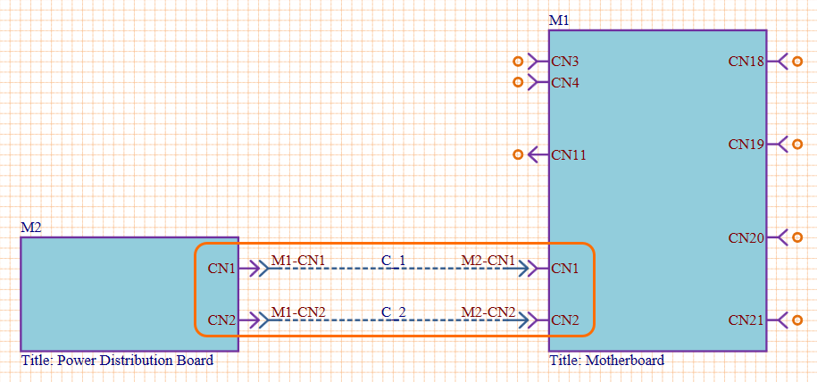
Multi-board PCB design tools can check net connectivity across different boards based on their mechanical interconnections via connectors or cabling. The DRC system in the multi-board domain ensures that the correct nets will be connected when each board in the system is brought together. On mating at the connector, logical net connection violations can be detected by the ERC engine.
When you have mating surfaces between connectors or edge connections, rules checking is all about preventing short circuits or mismatched connector pinouts.
You should still review your pinouts for their individual net connections and orientations as part of a regular design review, but a multi-board interconnect rules-checking feature helps you catch these in between review sessions. With a high pin count board-to-board connector, such as those involving hundreds of connections, this is a huge time saver as it could catch a very important error and possibly eliminate hours of rerouting.
Whether you need to build reliable power electronics or advanced digital systems, use the complete set of PCB design features and world-class CAD tools in Altium Designer®. To implement collaboration in today’s cross-disciplinary environment, innovative companies are using the Altium 365™ platform to easily share design data and put projects into manufacturing.
We have only scratched the surface of what’s possible with Altium Designer on Altium 365. Start your free trial of Altium Designer + Altium 365 today.
About Author
Related Resources
Related Technical Documentation
Table of Contents
Design to Release, Without the Friction
- Keep reviews tied to the right version
- Reduce handoff confusion and rework
- Spot sourcing and release risk earlier
- Work solo, share when needed
Get Started
Thank you, you are now subscribed to updates.

