


Top 3 Multi-Board PCB Connectivity Errors

At a Glance
Multi-board PCB design errors almost always come back to some element of connections between boards. Here’s how to fix them.


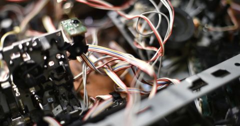
Imagine the terror: you power up your new multi-board system, only to find shorts and opens where you didn’t expect. Suddenly nothing is working as expected, or possibly worse, the boards get a little too hot for their own good.
Most multi-board PCB design errors boil down to some variation of “the wrong nets are connected” or “it doesn’t fit in its enclosure” or “the board orientation is wrong,” all of which could result from either mechanical or electrical mistakes (or both). These are symptoms, not causes… the root cause is often something simple that can be caught with a logical check combined with a checking a 3D mechanical model.
So with this in mind, here are some of the most common problems in multi-board electrical connections.
Multi-Board Connection Problem #1: Wrong Keyed Connector Orientation
Multi-board assemblies often use keyed connectors, which will regulate how two mating connectors must be oriented. The two connectors will then determine the orientation of the two mating boards. When a multi-board's connector orientation is backwards, the resulting orientation of the boards will also be backwards.
There are a few problems that could cause wrong keying:
-
The pin 1 indicator was in the wrong location
-
Pin 1 indicator is missing completely
-
No assembly outline or silkscreen outline showing orientation
-
No square pad showing orientation (for through-holes)
-
Pad orientation is reversible, but keying is not
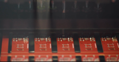
Vertically oriented SMD connectors with no board-level keying mechanism are the most susceptible to this problem. This is because the multi-board connector orientation could be reversed in the PCB footprint. If your assembly documentation does not show an orientation, or if there is no orientation indication in the PCB silkscreen, then there is a danger this error will occur during assembly.

The square pad indicates the correct orientation for this keyed connector
Multi-Board Connection Problem #2: Shorts/Opens on Unkeyed Connectors
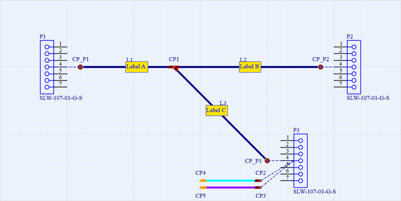
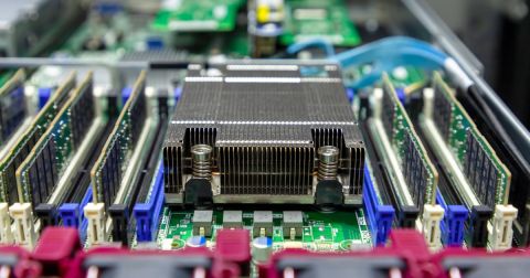
Not all multi-board connectors are keyed; some are not keyed and will therefore have a reversible footprint, even if the pinout is not reversible. The benefit of an unkeyed multi-board connector is that the connecting cable can be reversed; the same applies for unkeyed board-to-board connectors. The simplest is a pin header, but more advanced systems will use a mezzanine connector, such as the Hirose connector shown below.

If these reversible mating Hirose connectors have a reversed pinout, then they will force the two boards into the wrong orientation
When two boards are connected with a non-keyed connector and a non-rotatable pinout, the result might not be correct. For example, either the pinouts will not match, or the mating board orientation will be incorrect with pinout match. Either way, it means the pinout on one side of the multi-board interconnect needs to be rotated 180 degrees.
Multi-Board Connection Problem #3: Backwards ZIF/LIF or Flex Ribbon Connector
Zero insertion force (ZIF) connectors, low insertion force (LIF) connectors, or flex ribbon connectors are used to connect a board to an FPC cable, which might be a simple flex PCB or a rigid-flex PCB. Flex PCBs that are used for multi-board interconnects may have exposed contact pads through the coverlay on one side of the PCB. These exposed contact pads will make the mating connection to a ZIF connector contact.
If the coverlay opening is on the wrong side of the flex ribbon, then the mated board will have to be upside down in order to make electrical contact. For a double-sided ZIF connector, if the pinout is backwards, you would get the same problem.

If flex ribbon contacts are on the wrong side, the mating board orientation will be upside down
Logical Checking for Interconnects
How do you avoid these multi-board problems? One important point is to perform a thorough connector and cable orientation check as part of your multi-board PCB design review. This includes many of the following points:
-
Have all multi-board pinouts been verified to have correct net naming and connections?
-
Are pin 1 markings present on keyed connectors?
-
Are multi-board pinouts correct on unkeyed (rotatable) connectors?
-
Does the STEP model in your 3D PCB view match the mechanical keying orientation?
-
When you push to MCAD, do keyed connector orientations line up in 3D?
-
Are pins visible on ZIF connectors and are they in the correct spot?
-
Are FPC cables or connectors oriented with the right bend and board orientation?
It sometimes helps to actually order sample connectors once they are added to the multi-board design so that you can clearly see how the connectors will be oriented. It also never hurts to make a paper mockup with the connector so you can see the proposed assembly!
Board-to-board connectors, cables, and harnesses have to be part of the logical net connectivity checking process, but not all multi-board PCB design systems have these features. With a harness design tool for logical connection checking, and with an MCAD collaboration tool for 3D orientation checking, both aspects can be verified quickly by an engineering team.
Thankfully, you don’t have to guess the connections between PCBs in a multi-board assembly. With Altium’s ECAD and MCAD collaboration features, mechanical and electrical designers can work together seamlessly. To support collaboration in today’s cross-disciplinary environment, innovative companies rely on Altium to easily share design data and bring projects into manufacturing.
Interested in exploring multi-board PCB design? Discover how Altium Develop makes it easy to create complex designs and error-free system interconnections.
About Author
Related Resources
Related Technical Documentation
Table of Contents
Design to Release, Without the Friction
- Keep reviews tied to the right version
- Reduce handoff confusion and rework
- Spot sourcing and release risk earlier
- Work solo, share when needed
Get Started
Thank you, you are now subscribed to updates.


