


Design Phase – Lid Assembly Mechanics Part 3


Milestone
1
2
3
4
5
6
7
8
Design Phase – Lid Assembly Mechanics Part 3
| Created: November 23, 20239
10
11
More Milestones
| Coming soonWelcome to the third part of the open-source laptop lid assembly design! In the last installment, we looked at one possible way to integrate the webcam module and all the connected sensors into the bezel of the laptop lid.
We have identified several challenges with the approach presented in the previous article. The additional assembly and manufacturing complexity associated with using a flexible PCB led us to another option using only a rigid board. Now, let's see how this implementation works.

Webcam PCB mounted inside the screen bezel
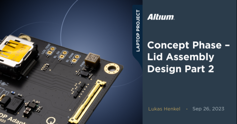
Ambient light sensor daughter board
One challenge we´ve already identified is the need to decrease the distance between the top side of the ambient light sensor and the opening in the display glass. The maximum distance between the light sensor and the cover glass is given by the opening diameter of the viewing window in the display glass. We looked at this relationship in part 1 of the lid assembly design update series.
Because we have to keep the opening in the silkscreen on the display glass as small as possible to ensure it is not visible, it must be limited to 1 mm in diameter. This means the maximum distance from the top of the sensor to the display glass must equal 1.2mm. Because we’re using a rigid webcam PCB, the board sits four millimeters below the coverglass. The light sensor is only 0.8mm in height, meaning we must somehow bridge a gap of roughly 2mm.
2mm is a standard thickness for PCBs. We can mount the ambient light sensor with it's decoupling capacitor and two pull-up resistors for the I2C bus on a small PCB. Then, we can solder the whole module onto the webcam board.
If we decide to switch out the light sensor in future revisions, we can modify the small module without having to redesign the webcam board.
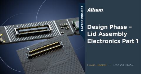
The design for the sensor module is a simple two-layer board with the light sensor and passive components on the top side and the contact LGA pads on the bottom side. Here, you have a schematic and PCB Layout of this module:

The sensor is placed in the center of the module to serve as a pick-up point for the pick and place machine. Align the machine nozzle with the center of mass of the part to ensure reliable picking and placing, even at high acceleration rates on the PnP machine.
The webcam module's footprint extends beyond the ambient light sensor module outline. This allows the automatic optical inspection machine at the end of the assembly line to verify correct alignment and ensure sufficient solder on each pad of the module.

The footprint used on the webcam module extends beyond the outline of the light sensor module

Ambient light sensor module soldered onto the webcam board
Mounting point daughter board
We can adopt a similar daughter board approach for the mounting points. However, a challenge arises when securing thin PCBs to a thin metal piece in our design. Achieving the minimum required thread length for the corresponding screw diameter becomes a concern.
In addition to the minimum thread length, we have to keep in mind that threads can only be cut up to a certain depth into blind holes. The tap cannot cut threads all the way to the bottom of the hole, so a fixed offset must be added to the minimum thread length.
Taking all these factors into account, we need to provide a fairly deep thread for the mounting holes. The material thickness of the lid is fixed to 1mm, meaning we have to provide some kind of standoff for the mounting points.
We can address the issue by locally increasing the thickness of the webcam module through the addition of small daughter boards. These boards—also with a thickness of 2mm—feature copper pads on both the top and bottom sides. By employing the same stackup as the ambient light sensor board, we can manufacture these daughter boards on the same production panel.
With a local board thickness of 2.8mm we can now use a standard mounting hole in the display lid:

Webcam module mounting approach
Touch-key contact points
Now that the mounting situation for the webcam PCB and ambient light sensor is resolved, the remaining tasks include connecting the webcam board to the touch sensing pads and finding a solution for backlighting those touchpads.
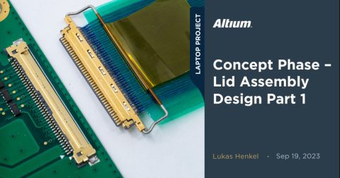
As shown in the previous article the FPC containing the touch sensing pads will be glued to the underside of the coverglass. On the FPC itself there is one contact pad with the dimensions of 1.7mm x 3.6mm for each touch sensing pad. We have a gap of 2.9mm for connecting to those pads.
The display glass should be easy to remove so we can´t use a permanent connection between the touchpad FPC and the webcam board. We could use an FPC connector, but that would make swapping the display glass quite difficult.
Instead, we can utilize spring-loaded SMD contact fingers. TE Connectivity offers a diverse range of these contact fingers at a reasonable price, especially for higher quantities.
The model used on the webcam PCB has the part number 3-2199250-3.

Contact fingers used on the webcam module
Our preference is to employ hard gold plating for the contact areas on the FPC. However, considering the limited movement and thermal cycles expected in this part of the system, there is a possibility of using standard ENIG plating instead. Nonetheless, thorough testing is imperative to ensure that this choice does not introduce any long-term reliability issues.
LED backlight diffusors
Next to the contact fingers are the RGB LEDs used for the backlighting of the touch icons. To provide a homogeneous illumination of the icons we need light diffusers that will sit on top of 1mm x 1mm LEDs.
SLA 3D printed parts are the favorable option for this application. Given the small size of the diffusers, it's feasible to print 600 pieces per batch. The total handling time—including post-processing—is only 2 minutes, with a printing time of 10 minutes. This makes 3D printing these parts an appealing choice for low-volume production runs as well.
The choice of resin will be very important for the optical properties of the diffusors and the long-term stability of the material. The choice of resin has not yet been finalized and will require several more tests.

Small 3D printed diffusors
The 3D printed parts will be press-fit onto the webcam board. An alternative option could involve using a small amount of glue, necessitating an additional processing step in the assembly process. Although gluing might increase handling time slightly, it could be a more reliable choice, especially considering that the resin material is relatively brittle and may not be ideal for press-fit applications.
Further testing is needed to determine the most appropriate approach in this case.

3D printed diffusors mounted on the webcam board
An installation test of the complete webcam board in the updated lid tray (details will be provided in the next updates) indicates that all components fit seamlessly without any collisions or the need for rework.

Assembled display lid including the webcam board
In the next update, we will examine the schematic and PCB design of the webcam module. With only a few more details to sort out for the electrical design of the lid we are nearing completion of the first sub-system of the laptop design! Tune in when we tackle the laptop case design, trackpad, keyboard layout, and much more!

About Author
Related Resources
Related Technical Documentation
Design to Release, Without the Friction
- Keep reviews tied to the right version
- Reduce handoff confusion and rework
- Spot sourcing and release risk earlier
- Work solo, share when needed
Get Started
Thank you, you are now subscribed to updates.

