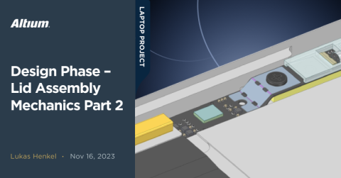
Design Phase – Lid Assembly Mechanics Part 1

Milestone
Design Phase – Lid Assembly Mechanics Part 1
| Created: November 3, 2023More Milestones
| Coming soonWelcome back to the open-source laptop project! In this update we are going to delve into the mechanical design of the laptop lid. Previously, we've explored which display panels are available and which would be the best fit for our application. Our search was successful as was the testing of the panel! Now the hard part begins: fitting everything into a system that is not only robust and functional, but also looks good.
While the title of this update is lid assembly mechanics, the line between electrical and mechanical design will get blurred quite a bit as you are about to see. However, that is the nature of such a project. Many decisions from the mechanical side have a direct influence on the electrical design and vice versa. Of course, we have to look at both sides at the same time.

Revision 1.0 of the webcam PCB
Material and manufacturing method
One of the first questions we need to answer is which material to use and how to manufacture the lid. This will have a direct impact on the shapes we can model into the lid and the associated costs. The last point is especially important since we are not looking at a very high volume product design at the time of writing. This limits the choice of manufacturing techniques, as processes involving high tooling costs are currently not an option. Sheet metal forming processes and any variant of casting techniques are therefore out of the question. Both manufacturing techniques require either expensive molds or stamping dies which are not cost effective for lower quantities.
The only viable option left that also offers a modern and robust look and feel is to machine the lid from a solid block of aluminum. CNC machined prototypes are relatively inexpensive and have a short lead time. The associated setup costs for machined parts are quite moderate due to modern CAM programs that can automate the programming of the machines to a certain extent.
Knowing that CNC machining will be the manufacturing process of choice, we can proceed with 3D modeling.
3D modeling of the lid
We will start with integrating the display panel first. For that purpose we can use the 3D STEP file of the panel and mounting brackets provided by Framework:
https://github.com/FrameworkComputer/Framework-Laptop-13/tree/main/Display
To start, the basic shape of the lid is just a rectangle with rounded corners and a pocket for the display panel:

Basic shape of the laptop lid
Since the whole part will be machined from a single aluminum block we can already design all the necessary features for mounting the display. Thanks to the pre-installed brackets on the display, we only need to provide a M2 internal thread and an alignment pin to mount the panel.
The height of the spacers is chosen so the panel does not lie flat on the aluminum tray. Instead there is a 1mm gap between the panel and the lid tray. This is a very important design feature that ensures the sensitive back of the panel never makes direct contact with the aluminum tray as it flexes when the lid is opened.
Bending of the laptop lid
Why would the laptop lid flex anyway, isn't the design goal to create a thin but robust lid that protects the display panel and doesn't bend during use?
While that may be the ideal case, in reality we have to find a good compromise between weight, thickness and stiffness. We could construct a very robust lid that doesn't bend at all but that would require a high material thickness which results in an overall increased thickness of the whole laptop and also adds a lot of weight. We want to make the lid as thin and light as possible while keeping deflection under control.
We can approximate the ideal material thickness by running some elasticity simulations on our CAD model. Since we know the approximate force that needs to be applied for opening the laptop we can use that as a simulation input to calculate the deflection of the lid. Since we do not yet know how the cover glass will be mounted, it will not be part of the simulation.

Illustration of the deflection of the lid when opening the laptop on one corner only
Integrating the webcam board
With the display panel in place and the correct material thickness figured out we can start to think about how we want to integrate the webcam PCB. As with most laptops, the webcam on our system sits centered above the screen in the screen bezel. This is the most intuitive placement for the webcam, but it leaves only a small gap between the panel and the lid for us to work with.
Before starting the design and placing the webcam and surrounding functional blocks in the CAD model, we first need to take a closer look at which components are found on the webcam board and what we need to consider when installing them. The following diagram shows that we have many more functional blocks besides the webcam that will sit on the webcam board:

Illustration of functional blocks placed on the webcam board
This is where it gets a little tricky when it comes to integrating the webcam PCB. We need to figure out the placement of four major functional blocks on the webcam PCB. Only one of these blocks can be adapted to our needs from a mechanical point of view, and that is the touchpads for activating and deactivating the privacy-critical functions. The other three function blocks mostly consist of individual components, such as the ambient light sensor. Let's take a brief look at the individual components to highlight the part-specific mechanical design requirements.
Ambient light sensor
The ambient light sensor from Vishay Semiconductors is a VEML3235. It comes in a small 2.0mm x 2.0mm x 0.87mm plastic package with a transparent top: https://www.vishay.com/en/product/80131/.

Closeup image of the ambient light sensor VEML3235
The optical sensing part of the die sits almost centered in the package. In order for the light sensor to work correctly in low ambient light levels it is necessary to place it as close as possible to a viewing window in the cover glass. The application note for the VEML3235 shows us how to calculate the window size depending on the distance of the part to the viewing window. The most important takeaway for us is that we need to get the sensor as close to the underside of the cover glass as possible. When we start designing the cover glass print, we need to go back to the application note and plan for the correct viewing window size.

Screenshot of the VEML3235 integration application note
Dual MEMS microphones
The microphone used in our system is a Knowles SPK0641HT4H-1. Two microphones will be used left and right of the camera to record stereo sound. The mounting situation for these two microphones is similar to the ambient light sensor. We want to place the microphone ports as close as possible to the corresponding hole in the cover glass. We would also like to place a foam gasket around the microphone to create a “guide” between the port in the cover glass and the microphone, but that will be part of the next revision of the microphone board.

MEMS microphone Knowles SPK0641HT4H-1
Webcam camera sensor
Last, but definitely not least, we have the OmniVision OV2740 webcam image sensor. The image sensor itself is only roughly 0.8mm in total thickness. Much more interesting for us now is the total height of the sensor plus the micro lens assembly that will sit on top of the sensor. There are a few lens types available but most of them are about 4mm in total height. This means that the image sensor must be located at least 4mm plus, some margin away from the underside of the cover glass.

OmniVision OV2740 image sensor
Webcam circuit board
We are now faced with the challenge of accommodating multiple components with different height requirements on a single PCB beneath the cover glass. There are several ways to accomplish this mechanically and electrically. We will explore at least two approaches with two revisions of camera PCB. One way to go about this is to use a flexible PCB with multiple stiffener types and thicknesses.

Multiple stiffener thicknesses create a board with multiple height levels
We are going to take a closer look at the PCB itself in the electrical design part of the lid. For now, let's focus on how the webcam PCB is mounted. The middle section of the board uses a 0.2 mm stainless steel stiffener. This middle section contains the image sensor and a board to board connector for connecting the webcam to the mainboard. Due to the low thickness of the stiffener we can meet the 4 mm height requirement of the camera lens by placing this section into a small pocket machined into the laptop lid.
In the image below, you can see two small alignment pins machined into the camera pocket. These will fit into the two small holes close to the left and right edge of the stainless steel stiffener. These pins will make sure that the board and especially the camera lens is aligned to the viewing window in the cover glass.

Webcam PCB with alignment holes
The picture above might already indicate how the whole board is mounted in the system. But, we still need to make sure the middle section of the PCB sits flush in the machined pocket and doesn't shift or even jump over the alignment pins when subjected to heavy vibration or shock.
This and many more questions will be answered in the next update! We still have to tackle a few challenges with the mechanical design of the lid before we can move on to the electrical design. I hope you'll follow along for the next updates as well!

