


Design Phase – Lid Assembly Mechanics Part 2


MIlestone
1
2
3
4
5
6
7
Design Phase – Lid Assembly Mechanics Part 2
| Created: November 16, 20238
9
10
11
More Milestones
| Coming soonWelcome to part two of the open-source laptop lid assembly design! In the last installment, we took a closer look at the basic design concept of the laptop lid and how we can integrate various sensors into the display screen.
We will follow down this same path, exploring two ways to integrate the sensor PCB above the display panel. This will have a direct impact on the remaining mechanical design of the lid, so let's see how we can approach this challenge.

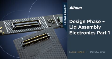
Webcam PCB with FPC to connect to the motherboard
First, you might recall we need to integrate multiple sensors; including two MEMS microphones, an ambient light sensor, a camera sensor, and seven capacitive touch pads. Additionally, we must ensure even backlighting for the touch pads with one LED per key. Each sensor has a unique height requirement, but they all need to be referenced to the underside of the cover glass. To mount all these sensors on a single PCB, we need to design a board with multiple height zones.
While the height requirements for the different sensors are clearly documented on the spec sheet, the backlit capacitive touch keys are a bit more complicated. Let’s address the capacitive touch sensors before focusing on the shape and integration of the webcam board.
Capacitive touch keys
The capacitive touch keys should allow the user to activate or deactivate certain privacy-critical functions such as the microphones, the webcam, or the WiFi connection. Activating or deactivating these functions is usually handled by the operating system. We want the ability to disable this software layer in the hardware—meaning we can interrupt power to these functional blocks without OS intervention—due to the software layer’s lack of transparency.
Typically, simple hardware switches or sliders are used to cover the camera or microphone. However, in our laptop design with an all-glass front, this is not an option. Instead, we will place backlit icons above the screen that can be activated or deactivated through capacitive touch sensing.
To achieve this result, we need a reliable way to sense touch through a coverglass thickness of 1mm or more. The ASIC used for touch detection must have higher sensitivity as the distance between the sensor electrode and the touch input increases. In a scenario with a substantial distance between the sensing pad and the touch input, not only does the sensitivity need to be very high, but the signal-to-noise ratio of the entire setup must also be sufficient. While it's possible to sense touch input over large distances, it becomes easier to trigger false touch actions. As the sensing distance increases, our actual useful signal moves closer to the noise floor of the sensing ASIC.
In order to use a low-cost sensing ASIC with a moderate sensitivity and signal-to-noise ratio, we need to place the sensing electrode as close to the touch input as possible.
In our case, this means putting the electrode right on the backside of the coverglass. All we need to do is attach a thin PCB on the backside of the glass. However, this introduces a new challenge: how do we illuminate the icons with a copper electrode in the way?
As a workaround, we will want to place copper along the outline of the icons while leaving a cutout in the board that is only 0.3mm larger than the touch icon printed on the coverglass.
The good news is that the manufacturing process of FPCs works in our favor. Unlike rigid PCBs, which use a milling tool of at least 1mm diameter, FCPs are cut with a laser. This allows for more intricate features without a minimum corner radius. Additionally, the laser path usually provides a tighter positioning tolerance to the copper artwork compared to traditional milling.

Icons printed into the coverglass

The touch sensing board with cutouts for the Icons
You will notice the cutouts of the touch icons align perfectly with the print on the coverglass. The corner radius within the icons is only 0.2mm in some places, which is no challenge for the laser cutting process.

FPC glued onto the coverglass
Another upside of using an FPC is they can be ordered with pre-applied 3M double-sided adhesive tape, meaning we no longer have to cut adhesive tape to size and apply it to the board before assembly.
We can use the DXF import function within Altium Designer to import the contours of the icons that were defined in the CAD tool. This saves us time spent defining the cutout regions for the backlighting.


Layout of the touch key PCB
The Layout screenshot above shows the touch pads around the associated Icons. The ground polygon is hatched to minimize the capacitance of the touch key with reference to ground in the regions where the pads overlap the ground pour.
The layout of the touchpad FPC can be found here:

PCB Integration Method #1
Now that we know how the touch sensing pads will be integrated into the system, we can take a closer look at how we want to integrate the whole webcam PCB.
In the previous update, we took a brief look at the FPC approach. A four-layer printed circuit board with different stiffener thicknesses was used to bring the board closer to the bottom of the cover glass where needed.
Three layer stack regions were defined in Altium Designer:

Layerstack Flex PCB
The leftmost and rightmost regions are equipped with a 1.2 mm thick FR4 stiffener. This reduces the distance between the microphones and the ambient light sensor to the coverglass to just 1.1 mm.
On the middle section, however, we used a 0.2mm stainless steel stiffener. The camera sensor and the FPC board-to-board connector will be mounted on this flat section.
By defining the right stiffener types and locations in Altium Designer, we can export the board in its folded mounting state:
Mounting this flex PCB comes with another set of challenges. The middle section does not have its own mounting hole. This is because there is not enough material thickness under the center section to use a mounting screw. However, this section also needs to be kept in place, so we need to find another way to achieve this.
The plan for mounting this section was to use a thin stainless steel part, bent to the desired shape by using a SLM 3D-printed metal bending tool.

CAD model of the mounting spring

3D rendering of the bending tool
As you’ve most likely already realized, this integration approach quickly becomes quite complex. There are several problems and cost driver associated with this method:
-
This approach only allows for a 4-layer flex PCB to keep the bending radii small. This makes the layout challenging and hard to adapt if further changes are needed;
-
Specialized manufacturing tooling for assembly of the flex PCB is needed due to the different stiffener thicknesses;
-
Specialized tooling is needed to bend the mounting springs for the flex PCB.
Assembling flexible circuit boards can be a challenge for some PCBA providers. The manufacturing equipment of most PCB assembly houses is catered towards flat rigid PCBs. Dealing with a PCB that is flexible and has different thicknesses requires additional fixtures in the manufacturing process.
Flexible PCBs can even make the manual assembly of circuit boards difficult. This is a good opportunity to learn which challenges would have to be dealt with in a production environment. Even though this flexible PCB didn't make it in the final laptop design, let's take a quick look at two manufacturing challenges the PCBA provider would have to deal with:
#1 Solderpaste printing
Paste printing requires the solder paste stencil to lay flat on the PCB surface. The squeegee which distributes the solder paste on the stencil applies a force to the stencil and the board underneath. The PCB needs to be able to support this force and must not bend during the printing process. For flexible PCBs with different stiffener thicknesses, a tool is needed to support the board. For the manual paste printing process, a 3D printed fixture can be used.

3D printed fixture needed for paste printing
#2 Assembly
As with the solder paste printing process, the pick-and-place machine also relies on the PCB being fixed securely in the machine. Usually tooling strips on the edge of a panel are used for this.
While the panel for the flex PCB does also provide these tooling strips they are not able to hold the board in place during assembly. An additional mounting plate is needed for assembling this flex board.
These fixtures are not always needed and depend largely on the machines used by the PCBA provider and on the geometry/layout of the panel. If stiffener sections can be connected together, it might be possible to assemble such a board without additional support hardware. In our case, however, this is not possible.

Panelized flexible PCBs
The aforementioned challenges, as well as the complexity added to the design by using a flexible PCB for the webcam module, are the reason why this approach was not used for the final system.
We will find out which approach was chosen instead and what problems came along with it in the next update! I hope you´ll follow along for the next installment of the open-source laptop project.

About Author
Related Resources
Related Technical Documentation
Design to Release, Without the Friction
- Keep reviews tied to the right version
- Reduce handoff confusion and rework
- Spot sourcing and release risk earlier
- Work solo, share when needed
Get Started
Thank you, you are now subscribed to updates.

