


Concept Phase – Lid Assembly Design Part 1


Milestone
1
2
3
4
Concept Phase – Lid Assembly Design Part 1
| Created: September 19, 20235
6
7
8
9
10
11
More Milestones
| Coming soonWelcome back to the open-source laptop project! In this update we will move one step closer to the design phase of the project. This is the first hands-on experience with one of the core components of the laptop — the display panel!
We will decide which display panel to use, how we can integrate it into the lid, and we are going to design, assemble, and test a small DisplayPort to embedded DisplayPort adapter to light up the screen for the first time.
When it comes to the electronics and hardware, there is much more to the lid of a laptop than just the display panel. The choice of panel will dictate how much space we have to implement features like microphones, webcam, and touch sensors as well as how sturdy the casing has to be.
Now that we know what to take care of first, let's get started!

Preview: almost fully assembled laptop lid
Which display panel is the right one?
The display is arguably one of the most important features of a laptop. This is the part that the user will interact with and rely on the most. Be it for professional work in a well-lit office space, creative writing on a sunny day in the park, or to watch videos in the evening in a comfortably illuminated living room. The laptop screen needs to work well in various lighting conditions and provide a good user experience for professional and casual use.
Laptops have long been used for more than just work. Scrolling through social media, gaming, and content creation are only a few of the many more use cases for a svelte mobile device. These points are also one of the reasons why the classic 16:9 aspect ratio is rarely found in today's laptops. While a 1920x1080 resolution still provides enough pixel density for most use cases, the aspect ratio is not a good middle ground to support the use cases mentioned above. The industry trend is heading in a different direction, let's take a look:

While I won't list every sleek and lightweight device available, it's evident that screens are becoming taller. This logical trend means content and programs can easily benefit from having a little more space in the Y-axis.
Keeping this in mind, we are looking for a screen with an aspect ratio that provides the same or more screen height than a 16:10 panel. At the same time, we are looking for a brightness of 400 nits or better with a resolution of at least 2.3 megapixels. Depending on the aspect ratio, the screen diagonal should be between 13" and 14.5".
I find panelook makes searching for screen requirements a lot easier.
We can configure the panelook search engine with the following data:

With these search criteria, the choice of 3400 panels with a diagonal between 13" and 14.5" collapses to a convenient 16 available panels. From these 16 panels one stands out in particular:

Available panels after filtering
The highlighted panel is available at a large number of suppliers, it has a screen resolution of 3.4MP, provides an aspect ratio of 3:2, delivers over 400cd/m² brightness and has an integrated backlight driver. We have a winner!
The best thing about this panel is that it is used in a fantastic product and is available as a stand-alone replacement part. Talking about the Framework Laptop 13":
https://frame.work/products/display-kit?v=FRANFX0001
The framework company also released the mechanical drawing for this display panel along with a 3D CAD file and the pinout for the eDP connector:
https://github.com/FrameworkComputer/Framework-Laptop-13/tree/main/Display
We can use this data as a starting point, and source the display panel directly from the framework for development purposes. The pre-installed mounting mechanism on the panel is also very handy.

Mounting mechanism Framework Laptop 13 panel
Testing the panel
Before we start to design the whole mechanics of the lid around this panel, we want to test it. Of course, we could just get the framework mainboard or an off-the-shelf embedded DisplayPort adapter for testing. But, since we will have to connect a display to our custom mainboard of the open-source laptop via an embedded DisplayPort interface sooner or later anyway, we might as well take the opportunity to gain some experience.
The goal is therefore to develop a very simple board to drive a 40-pin eDP interface. The board should be able to supply a voltage of 5V - 12V to drive the backlight of the panel, it should generate 3.3V for the logic voltage supply of the panel, generate a PWM signal for the dimming of the display and be able to connect to a computer via a full-size DisplayPort connector.
Designing a test adapter — schematic
The block diagram that covers the above functions is equally simple:

Block diagram DP to eDP adapter
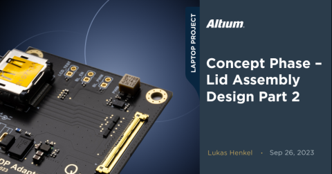
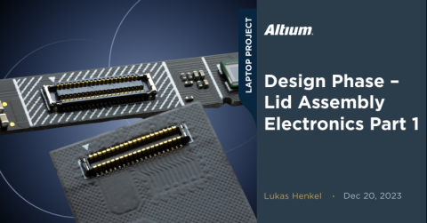
The board should interface with the screen through the same I-PEX connector which is used on the panel itself. This will make it easier to also test different display panels with the same 40-pin eDP connector. This connector is part of the I-PEX CABLINE®-VS family:
https://www.i-pex.com/product/cabline-vs
What we have here is a cable to board connector. A corresponding 1:1 micro-coaxial cable is available online in various versions. For this test board, we will use a long 0.5m cable from Esskabel:
https://www.esskabel.de/en/product/kab-i-pex-20453-040t-0500-1-1-flat/
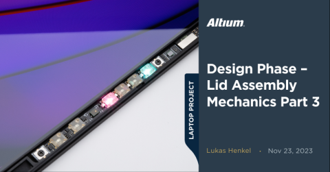
These laminated micro-coax cables are as the name implies made up of 40 tiny micro coaxial cables sandwiched between two plastic films. Such a cable is comparatively stiff and does not allow tight bending radii. This makes it rather unfit for use in a laptop. In addition, micro coax cables are quite expensive. If the cable does not have to bridge large distances, there are other ways to establish a connection. But we’ll touch more on that topic later. For initial testing, we will continue to work with the above-mentioned cable.

Micro-coaxial board to cable connector
Test adapter schematic

The first block of the schematic is the 3.3V power supply which provides the logic supply rail for the display. The input voltage for this PSU will be between 5V and 12V. The output voltage is 3.3V at a maximum current of 500mA. These requirements are very easy to meet with a small buck converter. To save time during the implementation as well as to not have to invest time in debugging, we’ll use an off-the-shelf module. These modules are often slightly more expensive than converters designed specifically for the target application as they must be suited to a wide range of applications. Special attention must be paid to the thermal performance of such high-density converter modules. The heat generating components like the switching MOSFETs and the power inductor are in very close proximity to each other while the thermal coupling of the substrate to the rest of the PCB is not ideal due to a missing thermal pad under the active die. This can quickly create a hot-spot if large currents are drawn from the module. However, for an application that is not cost sensitive or doesn´t have stringent dynamic requirements like our test adapter, these modules are a quick and easy way to generate a voltage rail.

RECOM RPL-3.0 DC-DC converter module
The module we are using is an RPL-3.0 from RECOM. This little device can provide up to 3A as long as the thermal derating limits are met. The schematic for the 3.3 V power supply is in large parts based on the reference design for the RPL-3.0:

Schematic 3.3V rail power supply
The input of the power supply gets protected with a fast-acting SMD fuse. In case we accidentally create a short circuit while performing some in circuit measurements this fuse will protect the upstream circuits from experiencing high currents for a long duration. In addition to the fuse, an unidirectional 12V TVS diode was placed parallel to the power connector. The TVS diode starts to conduct between 13.3V and 14.7V. If the applied input voltage gets too high the TVS diode will start to clamp the input rail which may cause a large current to flow through the fuse and therefore disconnect the circuit from the input. If a reverse voltage is applied to the input the TVS diode starts to conduct above ~0.7V which also causes a high current through the fuse and therefore disconnects the circuit.
With the design of the power supply finished let's have a look at the PWM generator. The LED driver in the display panel expects a PWM signal with a frequency of 200Hz – 2kHz. The high-level of this signal must not exceed 3.3V. We would like to adjust the PWM signal duty-cycle between 5% and 95%. The exact range is not particularly critical as we are mainly interested in comparing multiple panels at the same PWM level, as well as performing some comparisons at high and low duty-cycle values.
Generating such a PWM signal can be done in various ways. We could use a(t)tiny microcontroller, a comparator circuit, or a simple timer IC. As with the DC-DC converter, let's choose a simple solution that we know will work and is easy to implement without the need for firmware. The TimerBlox device family from Analog Devices is a good fit for this type of application. The LTC6992CDCB-1 creates a PWM signal with a duty-cycle that can be controlled by an analog voltage between 0 and 1V. Using a multi-turn trimmer resistor, we can easily create an analog voltage in that range. The frequency of the PWM signal can be set using an external resistor:
The ICs from the TimerBlox family are also available within LTSpice in case we want to verify that we´ve put the correct supporting circuitry around the IC.


SPICE schematic and Altium schematic PWM generator
All that is left to do now for the test adapter schematic is connect the full-size DisplayPort connector to the 40pin embedded DisplayPort connector. The data pairs as well as the AUX channel are connected one-to-one between the two connectors. The ESD diodes on the high-speed lines are not strictly necessary but are a good safety precaution for an experimental board like this adapter. The series 0R resistors can be used for measurement access or for inserting an in-line resistance, just in case…
It is worth mentioning that the pinout of a DisplayPort connection is not one to one on both ends. Instead, both the data pairs and the AUX channel are reversed in the link. This becomes important as our adapter needs to be treated as a DisplayPort sink device when it comes to the pinout of the connector.

DisplayPort Standard cable wiring. Source: iVANKY
All that's left to do now is put everything into one schematic, do a schematic review, and pass all the information into a PCB document.
That is exactly what we will be doing in the second part of this project update. Stay tuned for the assembly of the test adapter and the first light of the display panel! I hope you'll follow along for the next updates as well!

About Author
Related Resources
Related Technical Documentation
Design to Release, Without the Friction
- Keep reviews tied to the right version
- Reduce handoff confusion and rework
- Spot sourcing and release risk earlier
- Work solo, share when needed
Get Started
Thank you, you are now subscribed to updates.