


Preparing for Manufacturing with PCB Panelization Software

At a Glance
This guide shows which objects in your CAD tool are used to prepare a design for panelization and depanelization in PCB manufacturing.


The journey to physical circuit boards doesn't end after completing the PCB layout. Once the PCB layout is completed, it will need to be panelized before it can go into manufacturing. Manufacturers always build panels, not individual PCBs, and so the PCB layout data must be duplicated into an array in order to create a panel.
CAM software can be used to create panels by duplicating data from the PCB output files into an array format. Once in the array, multiple boards can be manufactured in a single panel, which optimizes the cost per PCB up to a maximum number per panel. Manufacturers generally build their own panels, but PCB designers can also build panels as part of production planning and optimizing board size. CAM software is not required for this; instead, a designer can build their own panel inside their PCB design software with the right features.
Get the Most From PCB Panelization
The entire goal of panelization is to fit the largest number of boards possible into a PCB panel. Because PCB cost is determined by panel cost, maximizing the number of boards per panel will minimize the cost per board at all production volume levels. In areas like consumer electronics or automotive, where PCB production is generally at high volume, this is very important for ensuring price competitiveness.
Due to the allowances required in some designs and the impact on cost per PCB, designers often need to estimate the number of boards per panel and do a draft panel design even if the manufacturer will create their own panel in CAM software. To accomplish this, your PCB design software can become PCB panelization software if it contains the right features.
Quick Estimates of PCB Yield Per Panel
Before doing any panel mock-ups in your PCB design software or drawing software, you can get a quick estimate of the PCB yield per panel. To do this, you need to first account for tooling rail allowances around the edge of the panel and the panel size available for your selected PCB material. The typical panel dimensions and allowances are:
- 18-in x 24-in standard panel size
- 1 to 1.5 in allowance around the panel edge for tooling rails
- 0.25 to 0.5 in allowance between PCBs for depanelization features
Using these dimensions and allowances, it is possible to estimate the total number of boards required in a panel. This can be done with a simple hand calculation or with a drawing application. CAM software or panelization features in your PCB design software allow you to experiment with board arrangements in a panel so that you can maximize the number of PCBs per panel. Based on these results, you can determine whether you need to reduce PCB size to hit a cost target.
Depanelization Features
Once PCBs are produced in a panel, they will need to be removed from the panel, and this requires some features to depanelize the PCBs. Depanelization often proceeds with the following features in the PCB:
- Mouse bites
- V-score lines
- Mechanical routing
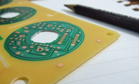
This route path and mouse bit array is used for depanelization.
PCB removal by routing is often the most efficient, and it is not something that would be performed by the end designer. When estimating PCB yield from a panel, the designer needs to select a tool size, typically 0.25-in diameter. However, mouse bites and V-scores allow the designer to detach PCBs from the panel by hand. PCB designers that are creating their own panel will need to place these elements in the PCB layout or output data; the table below shows the CAD objects that are required.
|
Mouse bites |
|
|
V-score |
|
|
Routing path |
|
Tooling Features
As mentioned above, a tooling rail is needed for fixing the panel and aligning multiple layers in the PCB stackup as the panel is built. Tooling features include mounting holes, test coupons built into the tooling rail, alignment pin holes, panel fiducials, and possibly silkscreen denoting panel part number.
The tooling features required in a panel depend on the production equipment being used for lamination. Tooling features are normally specified by the PCB manufacturer, so you should access their capabilities and panel requirements from their website. This will determine the required tooling hole sizes and locations on the panel edge. A manufacturer can often recommend what panel detachment features are needed in the tooling rail, so make sure to contact your PCB fabrication house to get their requirements or a panel template.
Designing a PCB Panel Using CAD Software
CAD software provides multiple routes to design a PCB panel. This can start from your PCB layout software and requires exporting a specific set of layers as a DXF file. Some design software provides a CAM editor that allows panel creation, or a panel can be created directly in the PCB editor by duplicating the PCB into an array.
|
CAD software for drafting |
Requires DXF export with specific layers |
|
CAM software |
Uses Gerber or ODB++ export |
|
PCB editor |
Uses the objects and board outline in your PCB layout file |
The image below shows an example panel created by exporting a DXF file for use in a drafting program. In this way, you are essentially creating a panel fabrication drawing which shows the PCB arrangement, tooling areas and features, and drill hit locations with a drill legend.
The same process can be performed in CAM software using your Gerber or ODB++ exports. CAM software allows a user to import these PCB design outputs and manipulate the outputs in preparation for production. This includes duplicating the PCB data into an array and applying tooling or detachment features to form the panel. CAM software allows for placement of drills in mouse bites and tooling rails, defining the score paths, and/or defining routing tool paths.

Not all PCB design software will support duplication of the design into a panel inside a PCB editor. However, Altium Develop includes the Embedded Board Array feature that allows easy duplication of a PCB into a panel design. No PCB design outputs or DXF exports are needed to create a panel with the Embedded Board Array tool. Once the PCB array is designed in the panel, tooling features can be placed and design outputs can be generated for the entire panel.
To learn more about panel creation using the Embedded Board Array, watch the video below. This video runs over the definition of tooling features in the PCB editor and shows how to duplicate a PCB layout into an array for a panel design.
Whether you need to build reliable power electronics or advanced digital systems, use Altium’s complete set of PCB design features and world-class CAD tools. Altium provides the world’s premier electronic product development platform, complete with the industry’s best PCB design tools and cross-disciplinary collaboration features for advanced design teams. Contact an expert at Altium today!

About Author
Related Resources
Related Technical Documentation
Table of Contents
Design to Release, Without the Friction
- Keep reviews tied to the right version
- Reduce handoff confusion and rework
- Spot sourcing and release risk earlier
- Work solo, share when needed
Get Started
Thank you, you are now subscribed to updates.


