


DDR5 PCB Layout, Routing, and Signal Integrity Guidelines

Release of the DDR5 standard was announced in July 2020, about 18 months after the announced development of the first RAM module following the proposed standard. The standard allows peak speeds in excess of 5200 MT/sec/pin (compare that to 3200 MT/sec/pin with DDR4), with JEDEC-rated speeds up to 6400 MT/sec/pin and channel bandwidth increased up to 300 GB/s. Demand for this new generation of memories with 8, 16, and 32 GB capacities should outpace that for earlier generations as the technology becomes more commercialized.
The faster speeds, lower supply voltages, and higher channel losses create strict margins and tolerances in DDR5 PCB layout and design, but the signal integrity of DDR5 channels can still be evaluated with common signal integrity metrics. There is a lot to cover in this area, but in this article we’ll focus on the essential DDR5 PCB layout and routing guidelines that will help ensure signal integrity in DDR5, as well as the important signal integrity metrics in DDR5 channels.
DDR5 Eye Diagrams and Impulse Responses
There are two important simulations that are used to examine signal integrity in DDR5 channels: an eye diagram and impulse response. An eye diagram can be simulated or measured, as can an impulse response in a terminated channel. Both measure the capability of a channel to trasmit a single bit and a bitstream through a channel, and they allow the analytical model for a channel to be evalutaed in terms of causality. The table below summarizes the important information that can be determined from these measurements/simulations.
|
|
|
|
|
|
|
|
|
|
|
|
To learn more about some of the technical specifications of DDR5 channels in a brief comparison with earlier DDR generations, take a look at this article.
Eye Diagrams in DDR5 Signal Integrity
The main metrics extracted from an eye diagram are the eye opening and the bit error rate (BER). The eye opening can be traced out in the center of the eye and is typically used as a measure of channel quality. The important points that can be directly extracted from signal crossings are the ampitude jitter and timing jitter, both being indicative or ISI and some sources of distortion or losses. When timing jitter and amplitude noise are high, the eye diagram will be more closed. Improving the main signal integrity metrics in the channel (losses, dielectric dispersion, extending impedance matching bandwidth to higher frequencies) should improve both of the aforementioned metrics and thus open the eye more fully, leading to lower bit error rate.

Impulse Responses in DDR5 Signal Integrity
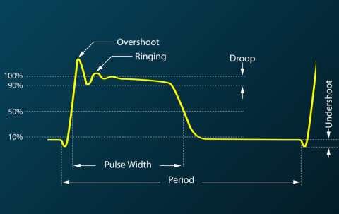
Impulse responses consider the response of a channel in isolation when sourced with a fast pulse. While it is important to evaluate a pseudorandom bitstream like you would do in an eye diagram, an impulse response is more fundamental. It reveals information about how a channel transmits a single bit with particular edge rate (bandwidth) through the channel and to the receiver. The channel's impulse response will depend on the channel impedance, the termination bandwidth compared to the signal bandwidth, total losses in the channel, and dispersion. DDR5 signals have greater focus on reflection-dependent loss at the receiver than typical serial channels, which can be seen in the edge rate of an impulse response.

The important reason to use an impulse response simulation for a proposed DDR5 channel design or from an extracted channel model is to evaluate channel causality. The model determined from channel S-parameters could produce a non-causal response in the channel, and so some correction (windowing) would be needed to modify the channel model if non-causal artifacts are present. Read more about this in a recent article from Jason Ellison.
An SI analysis process in a DDR5 channel (or any other high-speed channel) would include:
- Channel design and test/simulation
- Model extraction from simulated full-wave impulse response, or from S-parameter measurements
- Model causality verification and correction
- Eye diagram simulation and testing
- Modify channel design
- Repeat until channel compliance is achieved
Decision Feedback Equalization (DFE) on DQ Lines
One of the biggest changes (in my opinion) to DDR architecture is the use of decision feedback equalization (DFE) to overcome channel losses and dispersion in the DQ lines in a DDR5 bus. Conceptually, the easiest way to overcome distortion in digital signals is to pass the attenuated signal through a high pass filter. This is why a parallel RC filter can be used as a simple equalizer. But in DDR5, where the digital signal bandwidths are much higher, DFE is more effective and is incorporated in the receive side of a channel. The reason DFE is used is that these channels may need to be rather short compared to serial channels, and DFE is effective when reflection losses are significant in overall channel losses.
DDR5 will continue to include single-ended nets, but ideally they should have shorter channel length than an earlier DDR generation. At the high speeds present in DDR5 channels, reflection-dominant behavior and dispersion combine to produce significant intersymbol interference (ISI) if traces are not properly terminated, as illustrated above in the section on impulse responses. ISI causes signal levels to appear distorted in addition to the shape distortion due to dispersion and reflections, and each digital pulse starts to look like a half-Gaussian pulse at the receive side in an unequalized channel. The end result is that the eye diagram for the channel starts to close as reflection-dominant losses and dispersion-related distortion accumulate.
In order to overcome signal distortion and ISI, an equalization scheme is incorporated into the DRAM architecture, either at the transmit or receive side, similar to the case of some DDR3 and DDR4 controllers. Decision feedback equalization (DFE) or continuous time linear equalization (CTLE) can be used at the receive side, or feed-forward equalization (FFE) can be used at the transmit side. Note that CTLE is not ideal for reflection-dominated channels, thus DDR5 adopts DFE as the equalization method.
Eye diagram measurement.
DDR5 PCB Layout Guidelines for Reduced Signal Degradation
There are other sources of noise in DDR5 channels that become even more problematic than in previous generations, especially given the higher speeds required to accommodate the higher data rates and signal bandwidths. There are three main DDR5 PCB layout guidelines that will take priority in these designs.
- Precise termination and impedance control that extends to high bandwidths is required to suppress reflections within the required bandwidth.
- Power delivery is also critical in DDR5 PCB design. DDR5 modules will include a power management IC that receives 12 V and outputs 1.1 V to the DIMM ICs. This shifts power integrity to the DDR5 module level and away from the motherboard.
- Opt for shorter paths due to attenuation in DDR5 channels. A low-loss high speed laminate can be beneficial, or laminates with spread glass weaves to minimize fiber weave effects at high bandwidths.
On the simulation side, a post-layout crosstalk simulation tool that draws on IBIS models for your components can help you evaluate signal integrity in your DDR5 signal channels. Crosstalk can be used to determine if line spacing is appropriate given the stackup and distance to the reference for signal lines. The same simulation tool can be used for analyzing reflections, which is important in a reflection-dominated multi-drop topology found in DDR5, although this is less dependent on IBIS models and more dependent on modeling the signal injected into a channel, which could be done numerically in the right simulator.
GDDR5 for a GPU
The powerful PCB layout and routing tools in Altium are designed for applications like SerDes channels, DDR5 PCB design, and other advanced areas. Altium includes a powerful stackup manager with a field solver for controlling impedance in your board during routing, and you’ll have access to post-layout simulation tools that will help you spot signal integrity problems in your board.

About Author
Related Resources
Related Technical Documentation
Table of Contents
Get the Full Signal Analyzer Experience
- Turn SI analysis into fast, coordinated decisions.
- Your Agile Teams evaluation includes full access to Signal Analyzer.
Contact Us
Thank you, you are now subscribed to updates.

