How to Make a Bridge Rectifier For PCB Layout

Power conditioning is critical when working with PCBs and for delivering power to your components. This seemingly simple activity can create signal integrity problems if your components are not designed correctly, leading to bit errors or other signal problems during operation. Your design software can help you avoid problems that might arise when you build your own bridge rectifier circuit for your PCB. Simulation and power delivery tools help you visualize potential problems and allow you to correct your PCB and component design before you move to production.
ALTIUM DESIGNER
A fully unified, heavily rules-driven PCB design package with integrated component libraries.
With so many components to choose from in your PCB, design software companies and individual designers try to compile as many components as possible into component libraries. These component libraries contain everything you need to simulate a board based on your component models, build multi-part components, or add a new proprietary component for use in your designs.
Working with power conditioning and power conversion using a bridge rectifier circuit are widely used in a number of systems. Your PCB should make it easy to add these standard components to your PCB or build proprietary components for use across your designs. All these components should be accessible and searchable within your components library. The best PCB design software will integrate these component management features with your design tools, helping you maximize your design productivity.
The Best Component Selection Tools For Signal Manipulation
If you scroll through a component library, you’ll find a number of prepackaged bridge rectifier circuits that you can include in your PCB. You’ll also find a number of individual components that you can use to build your own bridge rectifier circuit for power conversion and conditioning. Whether your electronic circuits need a power supply built-in, or if you’re looking for electronic components like a voltage regulator, capacitor, or diode, having a strong library will help.
Whether it’s a wave bridge rectifier or full-wave bridge rectifier, being able to locate the components you need in any degree of simple circuit is outstanding. Finding the components you need takes a thorough component library with the best searching features, giving you the flexibility you need to design your PCB for your particular application.
Your Component Libraries and You
Your component libraries give access to a massive number of components, including everything you need to place a half-wave rectifier or full-wave rectifier on your next circuit board. Your component libraries should be extensive enough that they include pre-built rectifier circuits, yet still be adaptable enough that all of your other design tools can access information from this critical database.
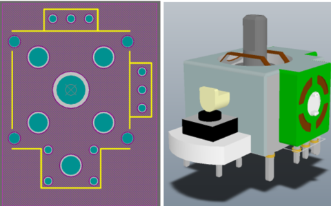
If existing components in a library don’t meet your power output or ripple specifications, your software should make it easy to design proprietary components. You’ll need to build a SPICE model, custom footprint, and 3D model for your proprietary component. All of this component data should integrate into the rest of your design tools, giving you the power to adapt your software to your specific application.
- Unified component libraries should give you the greatest level of design flexibility. This goes beyond including the most components; your component data should integrate with your other design features. See how unified design software and component libraries enhance your PCBs.
- Component placement and rectifier selection can make or break your routing strategy and signal integrity strategy. See how your component choices can help you prevent signal problems in your PCB.
- If existing components don’t meet your power output or ripple specifications, your software should integrate your proprietary components into your standard design features.
See how you can add custom components and multi-part components to your library.

A component comparison report in Altium Designer
Troubleshooting Signal Problems During the Design Phase
There are times where your PCB may have signal integrity, power supply, power conditioning, or power distribution problems, even if you followed standard and custom design rules. Although design rules are built to prevent these problems, it helps to be able to diagnose these problems before you receive fabricated boards. You should have a good idea of the signal integrity in your printed circuit board before they are sent off for production.
Whether through a voltage regulator, a capacitor, or even a MOSFET driver, you’ll want to make sure you have your output voltage and input voltage correct for your circuit diagram. When working through AC voltage, direct current, and voltage drop in your power supplies, you’ll want to be secure in your input voltage and output voltage calculations.
Simulation and analysis tools in your PCB design software let you diagnose and correct these problems before they create disasters. High speed, high frequency, and low power devices are all susceptible to various signal integrity issues that can cripple your PCB. You’ll need to take steps to correct any signal problems you discern from your simulation output. Your design software should give you the tools you need to diagnose these problems during the design phase instead of post-production.
Simulation and Analysis Tools For Power Electronics
Simulations can help you determine whether you need to include signal conditioning or power conditioning electronics in your PCB. They also let you directly view how these components and circuits affect signal integrity. This can help you narrow down potential causes of signal problems in your PCB, helping you locate the culprit. They can also help you determine whether you should design your own rectifier, regulator, and filtering circuits for your PCB.
- Whether you are building a high-speed device or you need to diagnose basic signaling problems, adaptable simulation and analysis tools can help you prevent disaster. See how signal integrity simulations aid design.
- Power delivery analysis is crucial when working with power conversion and power conditioning electronics. You’ll need to ensure that all components on your PCB will receive the power they require to run properly.
Learn more about diagnosing problems in your power delivery network.
- Working with power conversion components inevitably involves DC analysis in your power delivery network. Learn more about using power delivery analysis for DC power.
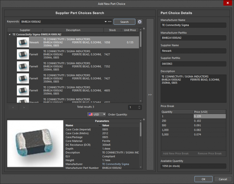
Locating components in Altium Designer
Power Conversion and Conditioning in a Unified Environment
Unified design flips the old design process on its head. Instead of switching between different software programs with different workflows, you can build the latest and greatest PCBs within a single interface. All your design, management, and analysis tools are contained in a single software package, and your features share data with ease.
This is the perfect environment to build and analyze PCBs with power conversion, signal conditioning, and power conditioning capabilities, not to mention high-speed or high-frequency devices. Information in your component libraries synchronizes easily with information in your layout, schematic, and design rules. All this data is then immediately accessible from your simulation tools, giving you the most productive design experience possible.
Unified Design and Data Management in Altium Designer
The design engine in Altium Designer is heavily rules-driven. Rules checking and compliance form the core of the design process, and the core design engine is built to interface with all of your component management and analysis tools. Altium Designer is the only PCB design platform that includes every design, component management, and deliverable generation tool in a single design interface. Other PCB design software programs separate these features into different programs with inconsistent workflow, hampering your productivity and management strategy.
Building the best mixed-signal boards and finding the right component for converting between AC and DC takes component libraries that interface directly with your design and analysis tools. Having access to the largest range of available components ensures that you won’t be pigeon-holed into making design choices that sacrifice the functionality of your device.
- Altium Designer unifies your design, analysis, and management tools within a single interface. Learn more about Altium Designer’s unified environment.
- Altium Designer’s design environment is heavily rules-driven, ensuring that your PCB will work as designed and allow you to diagnose potential problems. Learn more about rules-driven design in Altium Designer.
- If your PCB needs power conditioning, power conversion, and signal conditioning capabilities, Altium Designer gives you advanced simulation that can help you analyze signal integrity in your PCB. Learn more about signal integrity analysis in Altium Designer.
Working in a unified design environment means that your design features are built to work together in a single software platform. Your simulation and design tools integrate with your component libraries, and you can analyze the behavior of your bridge circuit and diagnose potential signal problems by directly accessing your component data.
Whether you are building circuits for quick prototyping or planning to begin high-volume manufacturing, Altium Designer has all the tools for your design needs. Altium provides every designer with resources the resources they need to be successful. You can access the AltiumLive forum, a comprehensive knowledge base, podcasts, and webinars provided by industry experts. Altium Designer never wants you to design alone and provides all the support you need.
The best design, component management, and simulation tools will help you find all the components you need for your PCB, as well as diagnose potential signal problems. Only Altium Designer supplies you with all these tools in a single software package. All these tools work together as part of a single platform. If separated features with inconsistent workflows are killing your productivity, then you need Altium Designer.


