Working with IPC Compliant Footprint Models

Industry standards have been a boon for designers and the electronics industry. Standards are important because they tell designers and manufacturers what to expect from certain component packages, and they assure designers that the components they select can be reused across their designs. It’s all about increasing productivity and ensuring your devices will work as you intended.
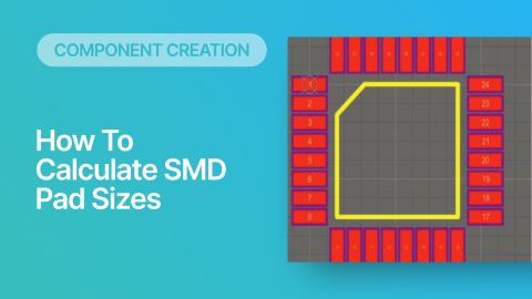
The IPC 7350 series of standards (specifically, IPC 7351B) specifies generic physical design parameters of land patterns for surface-mount components. Footprints used in IPC-compliant component packaging need to have a significant amount of information and it can be time-consuming to place all of this into a library for every component. In addition, unless you have the general footprint requirements memorized, you're probably reading dimensions off a datasheet for each component when creating a footprint.
To help speed up the footprint creation process, Altium Designer now includes a footprint generator that is compliant with IPC standards. This generator tool automatically performs all the mathematics required to create a footprint that is compliant with IPC standards. This guide will look at how to use the footprint generator for a custom CQFP package.
Creating a Component With an IPC-Compliant Footprint
Not all components are designed with IPC-compliant footprints. Thankfully, the best PCB design software packages have CAD tools that allow you to work with these components, so long as you apply some simple design strategies. For example, the pitch between landing pads may not be compatible with standard trace widths, and you’ll need to modify this setting in your design software if you intend to use these non-compliant components.
If you’re looking to avoid any placement or routing problems that can arise when working with custom components, you can skip the hassle and immediately create an IPC-compliant footprint for your component. The IPC Compliant Footprint Wizard is available in Altium Designer as an application extension. This wizard uses templates to generate compliant footprints for your components and saves a huge amount of time compared to creating a component manually.
To access the wizard, you’ll need to:
- Create a new Component (from File -> New -> Component on the top menu bar), or
- Create a new PCB Library and open the Footprint Wizard (Tools -> IPC Compliant Footprint Wizard from inside a PcbLib file)
Creating a new Component will allow you to store the new part in your Altium 365 Workspace. However, if you need to keep the component in a file-based library, you start from the Footprint Wizard inside a PcbLib file. Note that if you have the footprint in a PcbLib file, you can always migrate it to your Altium 365 Workspace later.
With this new window active, you’ll need to click on the “Tools” menu and select “IPC Compliant Footprint Wizard”. You’ll see options to create many different component footprints. For this example, we’ll use the CQFP package.
Selecting a component from the IPC Compliant Footprint Wizard in Altium
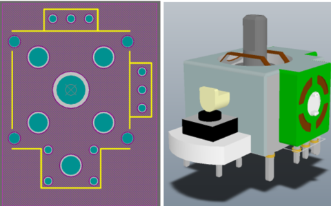
After you click “Next”, you’ll be able to define your package dimensions. You can select the package dimensions you need for your custom component. You’ll also get 2D and 3D previews of your component footprint and you can generate a preview of your STEP model for this component.
Defining the dimensions for a component footprint in Altium
The following screen will let you define minimum and maximum values for the lead width range and the number of pins required for this component. The wizard will calculate the required lead span range and the lead length range for the lead widths and number of pins you specified. You can also enter your values on this screen. Once you click “Next”, the wizard will show you the maximum and minimum gull-wing values for this component.
The next two screens allow you to define tolerances for this component. You’ll have some freedom to adjust these values based on the specifications of your component manufacturer. You’ll also see a screen that shows the pad dimensions for this component, and you’ll have the ability to define the silkscreen width, courtyard and assembly information, and component body information. Many of these values will be calculated for you based on the IPC specifications, and you should use these values if you want your component footprint to be compliant.
Additional information that can be automatically added are silkscreen, assembly, and courtyard outlines. Normally, the assembly outline can be created automatically when you create an Assembly View in a Draftsman document, but you will not be able to see it in a PCB layout. Therefore, it is only required if you want to see the assembly drawing view in the PCB layout and export a corresponding Gerber directly from the assembly layer data.
Courtyards are more like a boundary outline that can be examined visually to verify component clearance rather than using the design rules. Courtyard layers are not required, but many component footprints still use them because they allow immediate visual verification of clearance when placing components. Note that the standard component clearance rule does not require a courtyard definition and it will use the physical dimensions of the footprint elements to determine clearances.
Defining assembly outline and courtyard outline information and models in Altium
The final screen allows you to save your new component information in a PCB library. You can embed it in the current new library that is open in the background, or you can create a new library file for this component. You can also export a 3D STEP or Parasolid model for your component. Click “Next” and then “Finish” to complete the wizard.
Saving your component information and models in Altium
Once with wizard finishes processing, you’ll get access to 2D and 3D views of your finished component. Go to the “View” menu and select “3D Layout Mode” or press “3” on your keyboard to see your new component in 3D.
Using the Symbol Wizard for Your New IPC-Compliant Component
Creating a component footprint for a new component is not the whole story, you’ll also need to create a symbol for the component so that you can use the component in a schematic. First, you’ll need to create a new schematic library project. Click on File -> New -> Library -> Schematic Library to load this new library. After you create the symbol, you can then link the footprint from the PcbLib with the generated footprint. Note: you could also do this inside of an Integrated Library project in order to keep your symbol and footprint for a component in a single file-based library.
If you have the schematic symbol generation tool installed, you can access the Symbol Wizard to automatically generate a symbol for your IPC-compliant footprint. To access the Symbol Wizard, first you will need to open a new SchLib file. Click File -> New -> Library -> Schematic Library. Then select Tools -> Symbol Wizard.
You’ll see the symbol creation wizard appear. This dialog lets you define the pin layout that you’ll see in the schematic symbol. You can also choose the pin arrangement that appears in the schematic symbol. You can choose whichever arrangement will make it easiest to make connections with your other components.
If you have a small number of pins in your component, you can configure each manually if you like. However, for components with a large number of pins, you can write out the pin information in Excel and copy it into the pin table in the Symbol Wizard rather than defining each pin manually. This makes it very easy to define groups of pins quickly. You can also easily define the electrical properties (Input, Power, Output, I/O, etc.), pin reference designators, and display names.
Once you have built the symbol for your new part and defined the functionality of each pin, you can place it in the schematic library by clicking the “Place” button, followed by “Place Symbol”. This will place the symbol in your schematic library, and it will now be linked to your new compliant footprint.
Schematic symbol for the CustomCQFP component
To link the schematic symbol and the PCB footprint, you can use the Tools -> Model Manager option from inside the SchLib file, or click on the "Add Footprint" button at the bottom of the screen shown above. Using the Model Manager option will bring up the window shown below.
The Model Manager dialog in Altium
The footprint is linked to the schematic by clicking “Add Footprint”. Another window will appear that allows you to select a .PcbLib file from your local machine or the current integrated library project. Since the CustomCQFP.PcbLib file was already added to the project, you can click the “Browse” button and select the CustomCQFP component directly without searching for it on your hard drive.
Linking your PCB model to your schematic
If you want to have a single library package for a component part number, project, or group of compoennts, you can also create a new integrated library project. Click on File -> New -> Integrated Library to load this new project type. You’ll then need to add the PcbLib file and the SchLib file you created in the previous sections to this new library project. You can drag this file into the integrated library project if you still have it open in the navigator, or you can open this file manually.
Add Supply Chain Information
CAD tools will let you create whatever graphical information you like, but at some point you will have to source these parts so that they can be used in an assembly. This means supply chain information is needed, and the best choice for adding supply chain information to components is to use a direct link to a parts data provider like Octopart.
To add supply chain information to a new component, the best tool to use is the Supplier Links feature. When a supplier link is added to a component, the component's inventory, price, and lifecycle information will be displayed inside the Properties panel whenever you select the component. This will allow you to see the component's supply chain status in any of your design documents (schematics, PCB layout, or BomDoc file).
To add a supplier link, it is suggested to attach the information to a schematic symbol inside the component's SchLib file. To do this, open the SchLib file that contains your component, select the part, and scroll to the bottom of the Properties panel. Under the Part Choices section of the panel, there is a "Edit Supplier Links..." button. This will open the Supplier Links dialog.
Initially, the dialog will be blank for a new component. If you click the "Add" button, you will see the Add Supplier Links dialog appear (see image below). In this dialog, a user can enter the manufacturer part number into the search bar and select the supplier information that is returned in the search results. Click on the entry you want attached to your component and click OK.

Once you have attached the supplier link, the supply chain information will display in the Properties panel under the "Part Choices" section (lower-right corner of the image below). This information will automatically update each time you click on the part, and there will be no need to manually check with suppliers each time you want to verify that a part is in-stock.
Finding Pre-made PCB Footprints
No one likes making footprints, but luckily you don't have to reinvent the wheel for every component. Instead, you can access the Manufacturer Part Search Panel to help speed up the library creation process. From inside this panel, you'll be able to browse parts, find parts with attached symbols/footprints, and instantly view sourcing information in a single interface. This greatly speeds up the part search and selection process as you can instantly see the state of the component supply chain. You can also speed up your design time by picking components that have footprint data attached. Once you've identified the important components that need to have footprints created, switch over to the IPC-Compliant footprint generator to create library data for these components.

When you need to create component footprints, use the complete set of CAD tools in Altium Designer®. The PCB Editor in Altium Designer contains the industry's best tools for creating advanced electronics layouts and preparing your designs for manufacturing. When you’re ready to release these files to your manufacturer, the Altium 365™ platform makes it easy to collaborate and share your projects.
We have only scratched the surface of what’s possible with Altium Designer on Altium 365. Start your free trial of Altium Designer + Altium 365 today.


