Efficient Heat Dissipation with SMD Heat Sinks Keeps You From Dropping PCBs

In electronics, there is the possibility that your PCB can get pretty hot due to power dissipation in certain components. Whenever a component reaches an extreme temperature that goes beyond a component's safe operating range, its lifetime will be greatly reduced or the component may fail immediately. The heat-producing component being defective means the entire PCBA will need to be scrapped. There are many things to consider when dealing with heat in your board, and it starts with determining power dissipation in your design during schematic capture. If you happen to be operating within safe limits in a high power device, you might need an SMD heat sink on certain components. Ultimately, this could save your components, your product, and even the operator.
What Causes A PCB To Heat-Up and Need an SMD Heat Sink?
Electrical energy is converted to thermal energy due to resistive losses. All components, whether they are simple passives or complex logic circuits, will have some resistive losses. The consideration here is whether certain components will reach an unsafe operating temperature, as well as whether that heat can affect any nearby components. In addition, you might want to know some important information like reliability of any solder joints used on these components, reliability of nearby vias, and the reliability of the components themselves.
To start, you'll need to determine which components are candidates for applying a heat sink by looking at power dissipating and datasheets. Some of the major components that are at risk of failure from high power dissipation include:
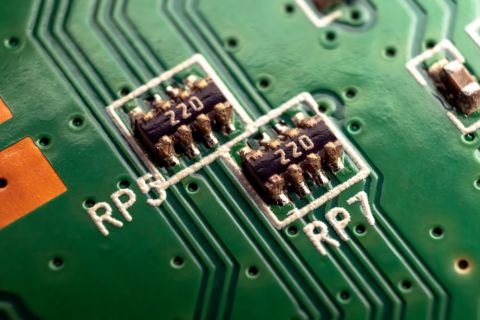
- Resistors or resistor arrays, specifically when used in power delivery
- MOSFETs used in power delivery or power regulation
- Linear regulators as these are designed to regulate voltage by dissipating heat
- Large digital ICs that provide the bulk of computing power
- Electromechanical components (motors, switches, etc.)
Some of these components may have some heat dissipation measures built into the component. For example, MOSFETs and linear regulators in TO packages or SOT packages will usually have a die-attached heat sink (see below). This sink can be mounted and soldered directly to a grounded pad in the PCB layout, giving a direct path for heat dissipation away from the component.
Depending on the power handled in these components, you might need an additional SMD heat sink that can be mounted directly to the component. What's the best way to attach these components, and when will you actually need them?
Determining Heat Dissipation Needs
Once you've identified the major components that will be responsible for the bulk of heat generation, you can use information from datasheets to estimate the temperature rise. The important specification to look for is the thermal resistance. A component's thermal resistance defines an expected temperature increase above ambient temperature. This is not the same thing as thermal conductivity, although you need to know thermal conductivity if you want to calculate thermal resistance. Thankfully, you won't need to do this, you can just use the thermal resistance data from your component datasheets.
The expected temperature increase can be calculated using the thermal resistance value provided in the datasheet and the power dissipation you expect in the design. For example, the popular LM7805 voltage regulator comes in multiple package options, each with different thermal resistance values. Typical values of thermal resistance between junction and ambient for power components are 20 to 30 °C/W. However, for the LM7805 in a TO-220 package, the datasheet lists the thermal resistance from junction to ambient as 54 °C/W! This is a huge level of heat dissipation: at 3 W power dissipation in the regulator (this will definitely happen at high input voltage, even if current is low), the design will likely fail as the regulator's temperature increases by 162 °C.

Sometimes, a datasheet will only list an absolute maximum power dissipation. This is sometimes the case where a component has some protection measures to help prevent failure. Some components will include a thermal shutdown value, so they will focus on absolute maximum temperature during operation. Another point to remember is that thermal resistance is a system-level metric; if you add in an SMD heat sink on the component, the thermal resistance from the package to ambient could be in the neighborhood of 10 °C/W, a big improvement over the typical junction-to-ambient thermal resistance value.
Best Ways to Mount an SMD Heat Sink
When we refer to an "SMD heat sink", we don't necessarily refer to a device that solders to the surface layer of a PCB. These devices can be mounted directly to a component package to provide high heat dissipation away from the component. They could also be mounted to the backside of a PCB or they could be used as a bridge to dissipate heat into an enclosure.
An SMD heat sink could be mounted mechanically (with a clip or screw), using a thermal compound (grease, etc.), or a thermal pad. High-power components might have a thermal tab or thermal pad that you would solder to a pad on the PCB (to a GND net), rather than to an SMD heat sink. However, you could still add an SMD heat sink to one of these components if needed; this is common in power delivery sections that use arrays of MOSFETs; a single large heat sink can be soldered across multiple components to dissipate more heat.
Given the demands on smaller PCBs, namely the need for greater processing power in smaller packages, heat is more problematic. In these small boards, there may not be room for fans, large heat sinks, or spacing between components to prevent heat diffusion around a board. When you place a board with high heat dissipation into a closed enclosure, the temperature of the major heat-generating components will often increase to much higher values. Of course, vents will help exhaust any airflow and will help keep the temperature down, but such an approach is only as effective as the heat dissipation techniques implemented on the PCB itself. For very high power designs that can't accommodate a fan, creative enclosure design will be the main driver of heat management.
An SMD heat sink is a great way to properly dissipate heat in high power components. As SMD heat sinks come in various sizes and shapes, you’ll want to ensure that the right footprint and mechanical model are created and that you have the best PCB design software in place to use it. When you need to access an easy-to-use PCB layout tool that includes everything needed to build high-quality manufacturable circuit boards, look no further than CircuitMaker. In addition to easy-to-use PCB design software, all CircuitMaker users have access to a personal workspace on the Altium 365 platform. You can upload and store your design data in the cloud, and you can easily view your projects via your web browser in a secure platform.
Start using CircuitMaker today and stay tuned for the new CircuitMaker Pro from Altium.


